
Page 195 - Mechanical design of microresonators _ modeling and applications
P. 195
0-07-145538-8_CH04_194_08/30/05
Microbridges: Lumped-Parameter Modeling and Design
194 Chapter Four
illustrated in Fig. 4.15. The torsional stiffness associated with midpoint
2 is calculated as
2
k = (4.94)
t,e C t
When the two segments are of constant cross section, the generic stiff-
ness of Eq. (4.94) becomes Eq. (4.28), which indeed defines the stiffness
of a constant-cross-section microbridge of length l.
The lumped-parameter torsional mechanical moment of inertia can
be expressed as
l
ȡt 2 2 2
J t,e = 12ฒ t dx (4.95)
f (x)w(x) w(x) + t
0
where the variable width w(x) is given in Eq. (4.93). When the two
segments are of constant cross section, Eq. (4.95) simplifies to Eq. (4.33)
which gives the effective torsional moment of inertia of a constant-
cross-section microbridge of length l. The torsional resonant frequency
can be calculated by means of Eqs. (4.94) and (4.95).
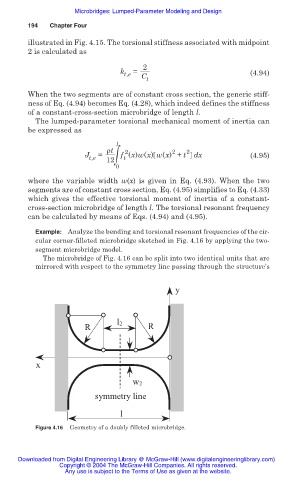
Example: Analyze the bending and torsional resonant frequencies of the cir-
cular corner-filleted microbridge sketched in Fig. 4.16 by applying the two-
segment microbridge model.
The microbridge of Fig. 4.16 can be split into two identical units that are
mirrored with respect to the symmetry line passing through the structure’s
y
l2
R R
x
w2
symmetry line
l
Figure 4.16 Geometry of a doubly filleted microbridge.
Downloaded from Digital Engineering Library @ McGraw-Hill (www.digitalengineeringlibrary.com)
Copyright © 2004 The McGraw-Hill Companies. All rights reserved.
Any use is subject to the Terms of Use as given at the website.