
Page 196 - Mechanical design of microresonators _ modeling and applications
P. 196
0-07-145538-8_CH04_195_08/30/05
Microbridges: Lumped-Parameter Modeling and Design
Microbridges: Lumped-Parameter Modeling and Design 195
one half unit basic unit # 2
symmetry line basic unit # 1 w2
l2/2
l2/2 + R R
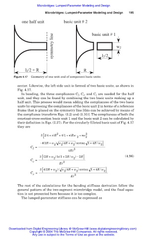
Figure 4.17 Geometry of one unit and of component basic units.
center. Likewise, the left-side unit is formed of two basic units, as shown in
Fig. 4.17.
In bending, the three compliances C l , C c , and C r are needed for the half
unit, and they can be found by combining the two basic units making up a
half unit. This process would mean adding the compliances of the two basic
units by expressing the compliances of the basic unit 2 in terms of a reference
frame that is placed on the symmetry line [this can be achieved by means of
the compliance transform Eqs. (3.2) and (3.10)]. The compliances of both the
constant-cross-section basic unit 1 and the basic unit 2 can be calculated by
their definition in Eqs. (2.27). For the circularly filleted basic unit of Fig. 4.17
they are
2
[
3 2(4+ ʌ)R +4(1+ ʌ)Rw 2 + ʌw 2 2
í4(2R + w ) w (4R + w ) arctan 1+4R / w
2 2 2 2
C =
l 3
4Et
[
3 (2R + w ) ln(1+2R / w ) í 2R (4.96)
C = 2 2
c 3
Et
[
3 4(2R + w ) / w (4R + w ) arctan 1+4R / w 2
2
2
2
C =
r 3
Et
The rest of the calculations for the bending stiffness derivation follow the
general pattern of the two-segment microbridge model, and the final equa-
tion is not presented here because it is too complex.
The lumped-parameter stiffness can be expressed as
Downloaded from Digital Engineering Library @ McGraw-Hill (www.digitalengineeringlibrary.com)
Copyright © 2004 The McGraw-Hill Companies. All rights reserved.
Any use is subject to the Terms of Use as given at the website.