
Page 198 - Mechanical design of microresonators _ modeling and applications
P. 198
0-07-145538-8_CH04_197_08/30/05
Microbridges: Lumped-Parameter Modeling and Design
Microbridges: Lumped-Parameter Modeling and Design 197
y
symmetry line
w
x O
C
l1 l2 l1
(a)
z
x
t FCz
l1 + l2/2
(b)
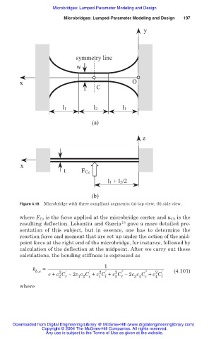
Figure 4.18 Microbridge with three compliant segments: (a) top view; (b) side view.
where F Cz is the force applied at the microbridge center and u Cz is the
18
resulting deflection. Lobontiu and Garcia gave a more detailed pre-
sentation of this subject, but in essence, one has to determine the
reaction force and moment that are set up under the action of the mid-
point force at the right end of the microbridge, for instance, followed by
calculation of the deflection at the midpoint. After we carry out these
calculations, the bending stiffness is expressed as
1
k =
b,e 2 ƍ ƍ 2 ƍ 2 Ǝ Ǝ 2 ƍ (4.101)
c + c C í 2c c C + c C + c C í 2c c C + c C
4 l
3 4 c
3 r
2 r
1 2 c
1 l
where
Downloaded from Digital Engineering Library @ McGraw-Hill (www.digitalengineeringlibrary.com)
Copyright © 2004 The McGraw-Hill Companies. All rights reserved.
Any use is subject to the Terms of Use as given at the website.