
Page 202 - Mechanical design of microresonators _ modeling and applications
P. 202
0-07-145538-8_CH04_201_08/30/05
Microbridges: Lumped-Parameter Modeling and Design
Microbridges: Lumped-Parameter Modeling and Design 201
The torsional resonant frequency of the microbridge is found by
combining Eqs. (4.114), (4.115), and (4.116) according to the definition,
namely,
6.93 GI t2/ ȡt(l +2C GI )
t
t2
2
Ȧ =
t,e
l 1
2 2 2
2 f (x) w(x) w(x) + t dx
t
0
(4.117)
l +l 2
1
2
2
2
+w (w + t ) f (x) dx
2 2 t
l
1
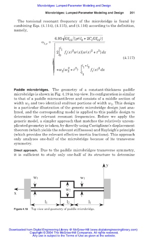
Paddle microbridges. The geometry of a constant-thickness paddle
microbridge is shown in Fig. 4.19 in top view. Its configuration is similar
to that of a paddle microcantilever and consists of a middle section of
width w and two identical end/root portions of width w . This design
2
2
is a particular illustration of the generic microbridge design just ana-
lyzed, and the corresponding model is applied to this paddle design to
determine the relevant resonant frequencies. Before we apply the
generic model, a simpler approach that matches the relatively uncom-
plicated geometry is taken, by directly using Castigliano’s displacement
theorem (which yields the relevant stiffnesses) and Rayleigh’s principle
(which provides the relevant effective inertia fractions). This approach
only analyzes one-half of the microbridge because of its transverse
symmetry.
Direct approach. Due to the paddle microbridges transverse symmetry,
it is sufficient to study only one-half of its structure to determine
y
w1 w1
w2
x
l1 l2 l1
Figure 4.19 Top view and geometry of paddle microbridge.
Downloaded from Digital Engineering Library @ McGraw-Hill (www.digitalengineeringlibrary.com)
Copyright © 2004 The McGraw-Hill Companies. All rights reserved.
Any use is subject to the Terms of Use as given at the website.