Page 207 - Mechanical design of microresonators _ modeling and applications
P. 207

0-07-145538-8_CH04_206_08/30/05


                                          Microbridges: Lumped-Parameter Modeling and Design

                              206   Chapter Four


                                    12.5
                                                                         6
                              ω t / ω b
                                      2.5
                                        1 1
                                                                        cw

                                                c l
                                                               2
                                                             3 3
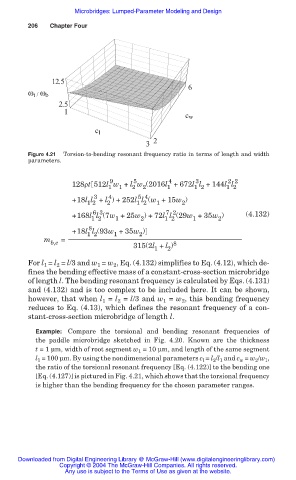
                              Figure 4.21  Torsion-to-bending resonant frequency ratio in terms of length and width
                              parameters.


                                                    9     5         4      3       2 2
                                          128ȡt 512l w + l w (2016l +672l l +144l l
                                                   1  1   2  2     1      1 2      1 2
                                                3
                                                   4
                                                           5 4
                                          +18l l + l ) +252l l (w +15w )
                                                                1
                                              1 2
                                                           1 2
                                                   2
                                                                       2
                                               6 3
                                                                   7 2
                                          +168l l (7w +25w ) +72l l (29w +35w )         (4.132)
                                               1 2
                                                                          1
                                                                                 2
                                                                  1 2
                                                     1
                                                            2
                                              8
                                          +18l l (93w +35w )
                                                            2
                                                     1
                                              1 2
                                  m    =
                                    b,e                              8
                                                          315(2l + l )
                                                                1  2
                              For l  = l  = l/3 and w  = w , Eq. (4.132) simplifies to Eq. (4.12), which de-
                                                     2
                                                1
                                      2
                                  1
                              fines the bending effective mass of a constant-cross-section microbridge
                              of length l. The bending resonant frequency is calculated by Eqs. (4.131)
                              and (4.132) and is too complex to be included here. It can be shown,
                              however, that when l 1  = l 2  = l/3 and w 1  = w 2 , this bending frequency
                              reduces to Eq. (4.13), which defines the resonant frequency of a con-
                              stant-cross-section microbridge of length l.
                                Example: Compare the torsional and bending resonant frequencies of
                                the paddle microbridge sketched in Fig. 4.20. Known are the thickness
                                t = 1 Ím, width of root segment w 1  = 10 Ím, and length of the same segment
                                l 1  = 100 Ím. By using the nondimensional parameters c l  = l 2 /l 1  and c w  = w 2 /w 1 ,
                                the ratio of the torsional resonant frequency [Eq. (4.122)] to the bending one
                                [Eq. (4.127)] is pictured in Fig. 4.21, which shows that the torsional frequency
                                is higher than the bending frequency for the chosen parameter ranges.
                           Downloaded from Digital Engineering Library @ McGraw-Hill (www.digitalengineeringlibrary.com)
                                      Copyright © 2004 The McGraw-Hill Companies. All rights reserved.
                                        Any use is subject to the Terms of Use as given at the website.
   202   203   204   205   206   207   208   209   210   211   212