
Page 208 - Mechanical design of microresonators _ modeling and applications
P. 208
0-07-145538-8_CH04_207_08/30/05
Microbridges: Lumped-Parameter Modeling and Design
Microbridges: Lumped-Parameter Modeling and Design 207
z
t1 t2
l1 l2 l1
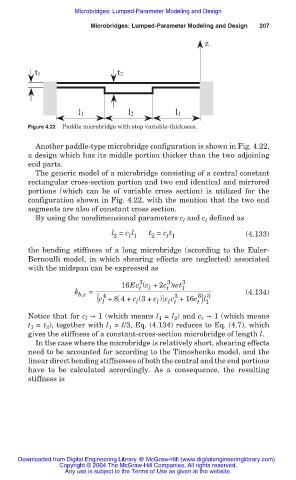
Figure 4.22 Paddle microbridge with step variable-thickness.
Another paddle-type microbridge configuration is shown in Fig. 4.22,
a design which has its middle portion thicker than the two adjoining
end parts.
The generic model of a microbridge consisting of a central constant
rectangular cross-section portion and two end identical and mirrored
portions (which can be of variable cross section) is utilized for the
configuration shown in Fig. 4.22, with the mention that the two end
segments are also of constant cross section.
By using the nondimensional parameters c and c defined as
t
l
l = c l t = c t (4.133)
2 l 1 2 t 1
the bending stiffness of a long microbridge (according to the Euler-
Bernoulli model, in which shearing effects are neglected) associated
with the midspan can be expressed as
3
3
16Ec (c +2c )wt 1 3
t
l
t
k b,e = 4 3 6 3 (4.134)
{c +8 4+ c (3+ c ) c c +16c }l 1
l
l
l t
l
t
Notice that for c l ඎ 1 (which means l 1 = l 2 ) and c t ඎ 1 (which means
t 1 = t 2 ), together with l 1 = l/3, Eq. (4.134) reduces to Eq. (4.7), which
gives the stiffness of a constant-cross-section microbridge of length l.
In the case where the microbridge is relatively short, shearing effects
need to be accounted for according to the Timoshenko model, and the
linear direct bending stiffnesses of both the central and the end portions
have to be calculated accordingly. As a consequence, the resulting
stiffness is
Downloaded from Digital Engineering Library @ McGraw-Hill (www.digitalengineeringlibrary.com)
Copyright © 2004 The McGraw-Hill Companies. All rights reserved.
Any use is subject to the Terms of Use as given at the website.