
Page 81 - Mechanical Engineer's Data Handbook
P. 81
70 MECHANICAL ENGINEER’S DATA HANDBOOK
If this distance is c then the balancing forces are
Force to accelerate piston F- -mrd
(approximately, see Section 2.4.1)
This introduces small errors due to moments
Maximum forces F, =mm2
(at crankshaft speed, which can be balanced)
r
which can be corrected for as shown in the figure. F, =ma2- (at twice crankshaft speed)
A further very small error remains and the process L
may be repeated until the desired degree of balance is
achieved. Eflect of conrod mass
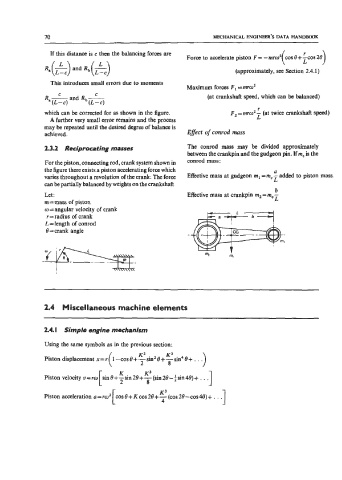
23.2 Reciprocating masses The conrod mass may be divided approximately
between the crankpin and the gudgeon pin. If mc is the
For the piston, connecting rod, crank system shown in conrod mass:
the figure there exists a piston accelerating force which a
varies throughout a revolution of the crank. The force Effective mass at gudgeon m, =m,- added to piston mass.
L
can be partially balanced by weights on the crankshaft.
b
Let: Effective mass at crankpin m2 = m,
m=mass of piston
w = angular velocity of crank
r = radius of crank
L=length of conrod
0 =crank angle
1
2.4 Miscellaneous machine elements
2.4. I Simple engine mechanism
Using the same symbols as in the previous section:
Piston
Piston velocity v = 1
t K3
1
Piston acceleration a=m2 cos8+Kcos2B+-((cos2B-cos48)+. . .
4