
Page 89 - Mechanical Engineer's Data Handbook
P. 89
78 MECHANICAL ENGINEER’S DATA HANDBOOK
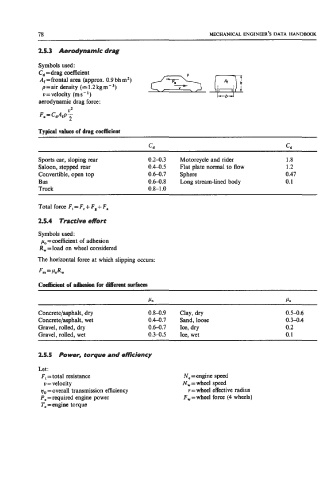
2.5.3 Aerodynamic drag
Symbols used:
C,=drag coefficient
A, =frontal area (approx. 0.9 bh m’)
p =air density (== 1.2 kg m - 3,
v=velocity (ms-’)
aerodynamic drag force:
02
F, = CdAfP T
Typical valws of drag coefficient
cd cd
Sports car, sloping rear 0.2-0.3 Motorcycle and rider 1.8
Saloon, stepped rear 0.4-0.5 Flat plate normal to flow 1.2
Convertible, open top 0.6-0.7 Sphere 0.47
Bus 0.6-0.8 Long stream-lined body 0.1
Truck 0.8-1 .O
Total force F, = F, + F, + Fa
2.5.4 Tractive effort
Symbols used:
po =coefficient of adhesion
R, =load on wheel considered
The horizontal force at which slipping occurs:
Flu = POR,
Coe&ie!nt of adbesion for different surfaces
PO PO
Concrete/asphalt, dry 0.8-0.9 Clay, dry 0.5-0.6
Concrete/asphalt, wet 0.4-0.7 Sand, loose 0.3-0.4
Gravel, rolled, dry 0.6-0.7 Ice, dry 0.2
Gravel, rolled, wet 0.3-0.5 Ice, wet 0.1
2.5.5 Power, torque and emciency
Let:
F, = total resistance Ne = engine speed
v = velocity N,=wheel speed
qo = overall transmission efficiency r = wheel effective radius
P, = required engine power F,=wheel force (4 wheels)
Te =engine torque