
Page 144 - Mechanical Engineers Reference Book
P. 144
Instrumentation 3/27
A. C. power A. C. power
I
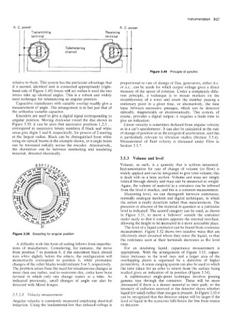
I I’ 1 I II Figure 3.49 Principle of synchrc
relative to them. This system has the particular advantage that proportional to rate of change of flux, generators, either d.c.
if a second, identical unit is connected appropriately (right- or ax., can be made for which output voltage gives a direct
hand side of Figure 3.49) forces will act within it until the two measure of the speed of rotation. Under a completely diffe-
rotors take up identical angles. This is a robust and widely rent principle, a technique is to mount markers on the
used technique for telemetering an angular position. circumference of a rotor and count the number passing a
Capacitive transducers with variable overlap readily give a stationary point in a given time, or alternatively, the time
measurement of angle. The arrangement is in fact just that of lapse between successive passages, which can be detected
the orthodox variable capacitor. optically, magnetically or electrostatically. This system, of
Encoders are used to give a digital signal corresponding to course, provides a digital output; it requires a finite time to
angular position. Moving clockwise round the disc shown in give an indication.
Figure 3.50, it can be seen that successive positions 1,2,3 . . Linear velocity is sometimes deduced from angular velocity
correspond to successive binary numbers if black and white as in a car’s speedometer. It can also be calculated as the rate
areas give digits 1 and 0, respectively, for powers of 2 starting of change of position or as the integral of acceleration, and this
at the largest radius. Black can be distinguished from white is particularly relevant to vibration studies (Section 3.5.4).
using six optical beams in the example shown, or a single beam Measurement of fluid velocity is discussed under Flow in
can be traversed radially across the encoder. Alternatively, Section 3.5.7.
the distinction can be between conducting and insulating
material, detected electrically.
3.5.3 Volume and level
Volume, as such, is a quantity that is seldom measured.
Instrumentation for rate of change of volume (or flow) is
widely applied and can be integrated to give total volume; this
is dealt with in a later section. Volume and mass are simply
related through density and mass can be measured as weight.
Again, the volume of material in a container can be inferred
from the level it reaches, and this is a common measurement.
Measuring level, we can distinguish between continuous,
normally analogue methods and digital techniques. in which
the action is really detection rather than measurement. The
presence or absence of the material in question at a particular
level is indicated. The second category can be used, as shown
in Figure 3.51. to move a ‘follower’ outside the container
under study so that it remains opposite the internal interface,
allowing the height to be measured in a more accessible place.
31 The level of a liquid conductor can be found from resistance
measurement. Figure 3.52 shows two resistive wires that are
Figure 3.50 Encoding for angular position effectively short circuited where they enter the liquid, so that
the resistance seen at their terminals decreases as the level
A difficulty with this form of coding follows from imperfec- rises.
tions of manufacture. Considering, for instance, the move For an insulating liquid, capacitance measurement is
from position 7 to position 8. if the outermost black should appropriate. With the arrangement of Figure 3.53, capaci-
turn white slightly before the others, the configuration will tance increases as the level rises and a larger area of the
momentarily correspond to position 6, while premature overlapping plates is separated by a dielectric of higher
changes of the other blacks would indicate 5 or 3, respectively. permittivity. A sonar-ranging system can also be used in which
The problem arises from the need for simultaneous changes at the time taken for an echo to return from the surface being
more than one radius. and to overcome this, codes have been studied gives an indication of its position (Figure 3.54).
devised in which only one change occurs at a time. As A sophisticated single-point technique involves passing
indicared previously, small changes of angle can also be gamma rays through the container. These will be more
detected with Moire fringes. attenuated if there is a denser material in their path, so the
intensity of radiation received at the detector shows whether
3.5.2.8 Velocity measurement liquid (or solid) rather than just gas is present. In Figure 3.55 it
can be recognized that the detector output will be larger if the
Angular velocity is commonly measured employing electrical level of liquid in the container falls below the line from source
induction. Using the fundamental law that induced voltage is to detector.