
Page 141 - Mechanical Engineers Reference Book
P. 141
3/24 Microprocessors, instrumentation and control
type is the linear variable differential transformer (LVDT),
where there are two further refinements shown in Figure 3.37:
1. A differential system is used so that the inductance of one
winding increases at the same time as that of another
decreases; and
2. By having a further winding, a mutual inductance or
transformer replaces the self-inductance.
These additions increase the magnitude and linearity of the
output and give an inbuilt bridge system, so increasing the
effective gauge factor. Figure 3.38 shows how small these
devices can be made.
While most practical devices employ ferromagnetic (iron)
cores, it is, in principle, possible to have an air-cored inductor
serving as a transducer.
3.5.2.3 Capacitance transducers
The electrical capacitance in farads between a pair of parallel Figure 3.38 A LVDT (courtesy Schaevitz)
plates (as shown in Figure 3.39) is
A
c = EO& - R
d
where E, is the permittivity of free space (= 8.9 X lo-'* F/m),
E is the relative permittivity of the material between
the plates,
A is the area of either plate, or of their overlap if they
are not exactly equal and opposite, and
d is the separation between the plates.
C can therefore be changed by changing either A or d. Since d
can be a millimetre or less, while the lengths involved in A are 0
likely to be a centimetre or more, and the percentage change
in C equals the percentage change in A or d, it can be seen that
variable-d transducers are more sensitive than variable-A Figure 3.39 Parallel plate capacitor
ones, i.e. those in which the overlap is changed. On the other
hand, the proportionality between C and A makes the second
type inherently linear, unlike the inverse C/d relationship
when the gap is varied. A differential arrangement, in which
the same movement increases one capacitance and decreases
another, is often used and can improve linearity.
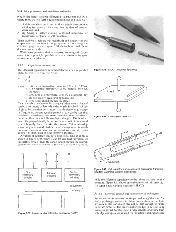
A variety of constructions have been used. One example is
shown in Figure 3.40, where it can be seen that movement of
an earthed screen alters the capacitance between the central,
cylindrical electrode and one of the outer, co-axial electrodes,
. P. /.
Figure 3.40 Cylindrical form of variable-area capacitance transducer
First Primary Second (courtesy Automatic Systems Laboratories)
secondary winding secondary
winding
winding
-uu
while the reference capacitance to the other electrode remains
constant. Figure 3.41 shows an embodiment of this principle,
Movement the super-linear variable capacitor (SLVC).
of core
3.5.2.4 Electrical circuits and comparison of techniques
Resistance measurements are simple and straightforward for
the large changes involved in sliding contact devices; the basic
accuracy of the transducer may not be high enough to justify
elaborate circuitry. The much smaller changes in devices using
strain gauges call for the use of bridge circuits, and some form
Figure 3.37 Linear variable differential transformer (LVDT) of bridge configuration is usual for inductance and capacitance