
Page 140 - Mechanical Engineers Reference Book
P. 140
Instrumentation 3/23
hazards include electrical interference and nuclear radiation.
The capabilities of particular items to withstand all these are
often not spelt out. Common sense is often called for to judge
what is reasonable to expect. Sometimes precise limits are
quoted by suppliers, but it should be noted that approaching
these limits closely may reduce accuracy and especially relia-
bility.
3.5.1.4 Frequency coverage
A simple description of what an instrument does may imply
that there is an indefinite amount of time in which to make a
measurement - the steady-state or d.c. behaviour. Sometimes
this is not the whole relevant story. There are certain devices
that cannot be used for steady-state measurements but only
for varying ones. There is always an upper limit to the
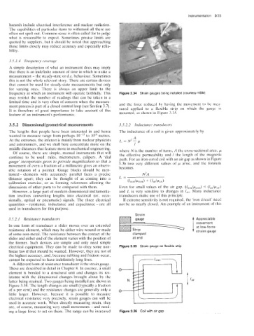
frequency at which an instrument will operate faithfully. This Figure 3.34 Strain gauges being installed (courtesy HBM)
may restrict the number of readings that can be taken in a
limited time and is very often of concern when the measure-
ment process is part of a closed control loop (see Section 3.7). and the force reduced by having the movement to be mea-
It is therefore of great importance to take account of this sured applied to a flexible strip on which the gauge is
feature of an instrument’s performance. mounted, as shown in Figure 3.35.
3.5.2 DimensionaVgeometrical measurements 3.5.2.2 Inductance transducers
The lengths that people have been interested in and hence The inductance of a coil is given approximately by
wanted to measure range from perhaps lo-’’ to 10” metres.
At the extremes, the interest is mainly from nuclear physicists L = N A ~ - ~
and astronomers, and we shall here concentrate more on the 1
middle distances that feature more in mechanical engineering.
Of course, there are simple, manual instruments that will where N is the number of turns, A the cross-sectional area, p
continue to be used: rules, micrometers, calipers. A ‘dial the effective permeability and I the length of the magnetic
gauge’ incorporates gears to provide magnification so that a path. For an iron-cored coil with an air gap as shown in Figure
movement of even a fraction of a millimetre gives an observ- 3.36 two very different values of p arise, and the formula
able rotation of a pointer. Gauge blocks should be men- becomes
tioned - elements with accurately parallel faces a precise N~A
distance apart; they can be thought of as coming into a L=
calibration exercise, or as forming references allowing the (lironlpiron) + (4dpair)
dimensions of other parts to be compared with them. Even for small values of the air gap, (Ziron/p+ron) (lalJpalr)
Q
However, a large part of modern dimensional instrumenta- and L is very sensitive to changes in lair. Many inductance
tion involves converting lengths into electrical (or, occa- transducers make use of this principle.
sionally, optical or pneumatic) signals. The three electrical If extreme sensitivity is not required, the ‘iron circuit’ need
quantities - resistance, inductance and capacitance - are all not be so nearly closed. An example of an instrument of this
used in transducers for this purpose.
Strain
3.5.2.1 Resistance transducers Appreciable
movement
In one form of transducer a slider moves over an extended at low-force
resistance element, which may be either wire-wound or made strains gauge
of some non-metal. The resistance between the contact of the clamped
slider and either end of the element varies with the position of at end
the former. Such devices are simple and only need simple
electrical equipment. They can be made to obey some non- Figure 3.35 Strain gauge on flexible strip
linear law if that should be wanted. However, they are not of
the highest accuracy, and, because rubbing and friction occur,
cannot be expected to have indefinitely long lives. /iron
A different form of resistance transducer is the strain gauge.
These are described in detail in Chapter 8. In essence, a small
element is bonded to a structural unit and changes its res-
istance with the dimensional changes brought about by the
latter being strained. Two gauges being installed are shown in
Figure 3.34. The length changes are small (typically a fraction
of a per cent) and the resistance changes are generally only a
little larger. However, because it is possible to measure
electrical resistance very precisely, strain gauges can still be
used in accurate work. When directly measuring strain, they
are, of course, measuring very small movements - and need-
ing a large force to act on them. The range can be increased Figure 3.36 Coil with air gap