
Page 137 - Mechanical Engineers Reference Book
P. 137
-
3/20 Microprocessors, instrumentation and control
il+
} vi
I
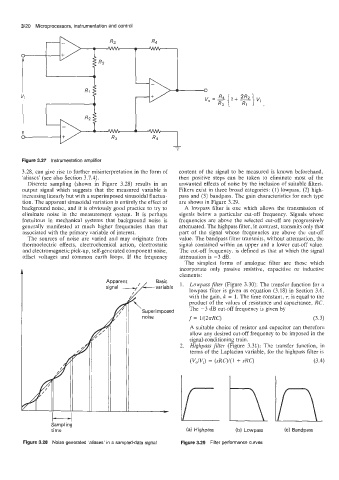
Figure 3.27 Instrumentation amplifier
3.28. can give rise to further misinterpretation in the form of content of the signal to be measured is known beforehand,
'aliases' (see also Section 3.7.4). then positive steps can be taken to eliminate most of the
Discrete sampling (shown in Figure 3.28) results in an unwanted effects of noise by the inclusion of suitable filters.
output signal which suggests that the measured variable is Filters exist in three broad categories: (1) lowpass, (2) high-
increasing linearly but with a superimposed sinusoidal fluctua- pass and (3) bandpass. The gain characteristics for each type
tion. The apparent sinusoidal variation is entirely the effect of are shown in Figure 3.29.
background noise, and it is obviously good practice to try to A lowpass filter is one which allows the transmission of
eliminate noise in the measurement system. It is perhaps signals below a particular cut-off frequency. Signals whose
fortuitous in mechanical systems that background noise is frequencies are above the selected cut-off are progressively
generally manifested at much higher frequencies than that attenuated. The highpass filter, in contrast, transmits only that
associated with the primary variable of interest. part of the signal whose frequencies are above the cut-off
The sources of noise are varied and may originate from value. The bandpass filter transmits, without attenuation, the
thermoelectric effects, electrochemical action, electrostatic signal contained within an upper and a lower cut-off value.
and electromagnetic pick-up, self-generated component noise, The cut-off frequency. is defined as that at which the signal
offset voltages and common earth loops. If the frequency attenuation is -3 dB.
The simplest forms of analogue filter are those which
incorporate only passive resistive, capacitive or inductive
elements:
Basic
1. Lowpass filter (Figure 3.30): The transfer function for a
lowpass filter is given as equation (3.18) in Section 3.6,
with the gain, k = 1. The time constant, r, is equal to the
p Superimposed product of the values of resistance and capacitance, RC.
The -3 dB cut-off frequency is given by
noise
f = 142.lrRC)
(3.3)
A suitable choice of resistor and capacitor can therefore
allow any desired cut-off frequency to be imposed in the
signal-conditioning train.
Highpass filter (Figure 3.31): The transfer function, in
terms of the Laplacian variable, for the highpass filter is
(VJVJ = (sRC)/(l + sRC) (3.4)
I
-
I----
Sampling
time (a) Highpass (b) Lowpass (c) Bandpass
Figure 3.28 Noise generated 'aliases' in a sampled-data signal Figure 3.29 Filter performance curves