
Page 132 - Mechanical Engineers Reference Book
P. 132
Interfacing of computers to systems 3/15
3.4.5 Machine tool interfaces
pin The control system for a machine tool slide is shown in Figure
3.23. Typically, there are two negative feedback loops, one for
0 Counter starts
Counter incrementing position and one for velocity in a cascade arrangement as
set to shown in the figure. The position sensor is usually an optical
zero grating device (or an inductosyn) and the speed sensor a
End of tachometer.
conversion The CNC interface initially has to decode the manual or
control tape input data. This consists of a sequence of com-
mands, including feed and speed data, essential dimensional
reference points and other constraints to be observed by the
machine during its operation. Pn operation, the interface is
required to monitor the slide position and speed and check
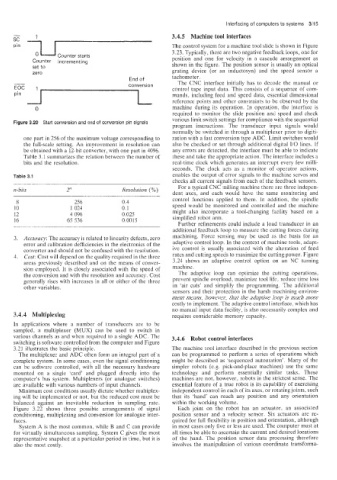
Figure 3.20 Start conversion and end of conversion pin signals various limit switch settings for compliance with the sequential
program instructions. The transducer input signals would
normally be switched in through a multiplexer prior to digiti-
one part in 256 of the maximum voltage corresponding to zation with a fast conversion type ADC. Limit switches would
the full-scale setting. An improvement in resolution can also be checked or set through additional digital I/O lines. If
be obtained with a 12-bit converter, with one part in 4096. any errors are detected. the interface must be able to indicate
Table 3.1 summarizes the relation between the number of these and take the appropriate action. The interface includes a
bits and the resolution. real-time clock which generates an interrupt every few milli-
seconds. The clock acts as a monitor of operator actions,
Table 3.1 enables the output of error signals to the machine servos and
checks all current signals from each of the feedback sensors.
n-bits 2” Resolution (YO) For a typical CNC milling machine there are three indepen-
dent axes, and each would have the same monitoring and
control functions applied to them. In addition, the spindle
8 256 0.4
10 1 024 0.1 speed would be monitored and controlled and the machine
12 4 096 0.025 might also incorporate a tool-changing facility based on a
16 65 536 0.001s simplified robot arm.
Further refinements could include a load transducer in an
additional feedback loop to measure the cutting forces during
3. Accuracy: The accuracy is related to linearity defects, zero machining. Force sensing may be used as the basis for an
error and calibration defficiencies in the electronics of the adaptive control loop. In the context of machine tools, adapt-
converter and should not be confused with the resolution. ive control is usually associated with the alteration of feed
4. Cost: Cost will depend on the quality required in the three rates and cutting speeds to maximize the cutting power. Figure
areas previously described and on the means of conver- 3.24 shows an adaptive control option on an NC turning
sion employed. It is closely associated with the speed of machine.
the conversion and with the resolution and accuracy. Cost The adaptive loop can optimize the cutting operations,
generally rises with increases in all or either of the three prevent spindle overload, maximize tool life, reduce time loss
other variables. in ‘air cuts’ and simplify the programming. The additional
sensors and their protection in the harsh machining environ-
ment means, however, that the adaptive loop is much more
costly to implement. The adaptive control interface. which has
no manual input data facility, is also necessarily complex and
3.4.4 Multiplexing requires considerable memory capacity.
In applications where a number of transducers are to be
sampled, a multiplexer (MUX) can be used to switch in
various channels as and when required to a single ADC. The 3.4.6 Robot control interfaces
switchiiig is software controlled from the computer and Figure
3.21 illustrates the basic principle. The machine tool interface described in the previous section
The multiplexer and ADC often form an integral part of a can be programmed to perform a series of operations which
complete system. In some cases, even the signal conditioning might be described as ‘sequenced automation’. Many of the
can be software controlled, with all the necessary hardware simpler robots (e.g. pick-and-place machines) use the same
mounted on a single ’card’ and plugged directly into the technology and perform essentially similar tasks. These
computer’s bus system. Multiplexers (or analogue switches) machines are not, however, robots in the strictest sense. The
are available with various numbers of input channels. essential feature of a true robot is its capability of exercising
Minimum cost conditions usually dictate whether multiplex- independent controi in each of its axes, or rotating joints, such
ing will be implemented or not. but the reduced cost must be that its ‘hand’ can reach any position and any orientation
balanced against an inevitable reduction in sampling rate. within the working volume.
Figure 3.22 shows three possible arrangements of signal Each joint on the robot has an actuator, an associated
conditioning, multiplexing and conversion for analogue inter- position sensor and a velocity sensor. Six a, Ptuators are re-
faces. quired for full flexibility in position and orientation, although
System A is the most common, while B and C can provide in most cases only five or less are used. The computer must at
for virtually simultaneous sampling. System C gives the most all times be able to ascertain the current and desired locations
representative snapshot at a particular period in time, but it is of the hand. The position sensor data processing therefore
also the most costly. involves the manipulation of various coordinate transforma-