
Page 129 - Mechanical Engineers Reference Book
P. 129
3/12 Microprocessors, instrumentation and control
Computer output port
I I
'Positioner'
Voltage/current current/pressure
converter converter
Flexible
Process flow -
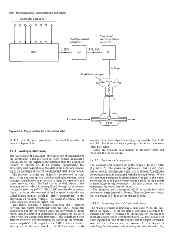
Figure 3.14 Digital interface for a flow control valve
the DAC and the valve positioner. The complete interface is essential if the input signal is varying very rapidly. The ADC
shown in figure 3.14. and S/H functions are often packaged within a composite
integrated circuit.
3.4.3 Analogue interfacing ADCs are available in a number of different forms and
these include the following.
The basic role of the analogue interface is one of conversion of
the continuous analogue signals, from process measuring
transducers to the digital representation that the computer 3.4.3.1 Staircase and comparator
requires to operate on. In all practical applications, the The staircase and comparator is the simplest form of ADC
monitoring and acquisition of the data is the necessary precur- (Figure 3.16). The device incorporates a DAC which gene-
sor to the subsequent control functions that might be actioned. rates a voltage increasing in small steps as shown. At each step
The process variables are ultimately represented as volt- the staircase input is compared with the analogue input. When
ages. Using the appropriate signal-conditioning circuits, these the generated staircase is approximately equal to the input,
voltages would ideally be processed to range between zero and the process is halted and a binary count is made of the number
some reference value. The final task is the digitization of the of steps taken during the process. The binary count from zero
analogue signal, which is accomplished through an analogue- represents the coded digital output.
to-digital converter (ADC). The ADC samples the analogue The staircase and comparator ADCs have relatively slow
signal, performs the conversion and outputs a digitally en- conversion times (typically, 20 ms). They are, however, cheap
coded binary number which is directly proportional to the and are essentially immune to electronic noise.
magnitude of the input voltage. The essential elements in the
signal train are shown in Figure 3.15. 3.4.3.2 Integrating type ADC (or dual slope)
This figure indicates a sample and hold (S/H) element
between the signal conditioner and the ADC. Since the The major elements comprising a dual-slope ADC are illus-
analogue input may be varying while the conversion is taking trated in Figure 3.17. At the start of conversion a voltage-to-
place, there is a degree of uncertainty in deciding the instant in current converter is switched to the integrator, causing it to
time which the output code represents. The sample and hold ramp up a slope which is proportional to Vi,. This occurs over
element removes this uncertainty by capturing the instanta- a fixed period of time at the end of which the input is switched
neous 'snapshot' of the input for the ADC to convert before over to the reference current source. At the instant of
moving on to the next sample. The S/H element is only switching the integrator output voltage is proportional to Vi,,