
Page 124 - Mechanical Engineers Reference Book
P. 124
Communication standards 3/7
anywhere within the above structure and varies from one of the two, with the bits denoting the characters of information
manufacturer to another. travelling sequentially along a single path. In the parallel
The display screen RAM is often fitted with a moveable method the data word is sent as a parallel code, invariably
boundary in order to set variable resolution modes for gra- 8-bits wide, resulting in a ‘bit parallel, byte serial’ transmission
phics. Typicaliy, the screen memory need only be 1K for a text of information.
mode to give a 40 X 25 character display. This would be
insufficient for computer graphics and a high resolution would 3.3.1 Serial communication
require 20K of memory to MAP the screen. It should be noted
that this greatly reduces the amount of RAM available to the Serial communication is the most common method used for
user. the interconnection of a microcomputer to the relatively slow
8080- and Z80-based systems have a distribution of memory peripheral hardware, or between two computers, when trans-
similar t(a that as shown in Figure 3.3. The ROM, however, is ferring a low volume of information. The (EIA) RS232C, or
usually low down and the RAM high up in the memory map. its successors the RS422 and RS423, is the most widely
The 16-bit PCs, with a 20-bit address bus, have 1M byte of adopted standard employed and connection between devices
addressable memory with the RAM comprising the first three is made via a standard 25-pin connector. This allows communi-
quarters and ROM occupying the last quarter. A general cation with one peripheral device only. Twenty-one of the
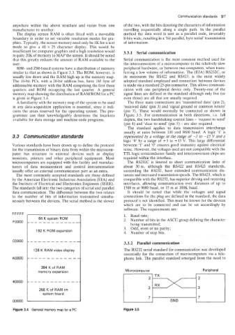
memory map showing the distribution of RAMiROM for a PC signal lines are defined in the standard although only five (or
is given in Figure 3.4. even three) are all that are usually required.
A familiarity with the memory map of the system to be used The three main connections are ‘transmitted data’ (pin 2),
in any dlata-acquisition application is essential, since it indi- ‘received data’ (pin 3) and ’signal ground or common return’
cates the areas reserved for the operating system. The pro- (pin 7). These would normally be connected as shown in
grammer can then knowledgeably determine the locations Figure 3.5. For communication in both directions, Le. full
zvailabie for data storage and machine-code programs. duplex, the two handshaking control lines - ‘request to send’
(pin 4) and ‘clear to send’ (pin 5) - are also required.
The standard applies to data transmission interchange
usually at rates between 110 and 9600 baud. A logic ‘1’ is
3.3 Communication standards represented by a voltage in the range of -3 to -15 V and a
logic ‘0’ by a range of +3 to +15 V. This large differential
Various standards have been drawn up to define the protocol between ‘1’ and ‘0’ ensures good immunity against electrical
for the transmission of binary data from within the microcom- noise. However, the voltages used are not compatible with the
puter bus structure to external devices such as display TTL logic semiconductor family and interconversion chips are
monitors, printers and other peripheral equipment. Most required within the interface.
microcomputers are equipped with this facility and manufac- The RS232C is limited to short communication links of
turers of data measurement and control instrumentation about 30m, although the RS422 and RS423 standards,
usually offer an external communication port as an extra. succeeding the RS232, have extended communication dis-
The most commonly accepted standards are those defined tances and increased transmission speeds. The RS423, which is
by the American Electronic Industries Association (EIA) and compatible with the RS232, has superior driving and receiving
the Institute of Electrical and Electronics Engineers (IEEE). interfaces, allowing communication over distances of up to
The standards fall into the two categories of serial and parallel 1500 m at 9600 baud, or 15 m at l0OK baud
data connmunication. The difference between the two relates It should be noted that while the voltages and signal
to the number of bits of information transmitted simulta- connections for the plug are defined in the standard, the data
neously between the devices. The serial method is the slower protocol is not identified. This must be known for the devices
which are to be connected and can be set accordingly by
software. The requirements are:
FFFFF 1. Baud rate;
2. Number of bits in the ASCII group defining the character
FOOOO
being transmitted;
3. Odd, even or no parity;
192 K ROM expansion
4. Number of stop bits.
COO00
3.3.2 Parallel communication
128 K RAM video display The RS232 serial standard for communication was developed
essentially for the connection of microcomputers via a tele-
AOOOO phone link. The parallel standard emerged from the need to
384 K of RAM
memory expansion Microcomputer Peripheral
1
TX
40000
256 K of RAM on
system board
7
00000 GND
Figure 3.4 General memory map for a PC Figure 3.5