
Page 126 - Mechanical Engineers Reference Book
P. 126
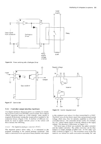
Interfacing of computers to systems  319
           P +
                                                        Load
                                                        SUPPlV


      Input signal                       7-                       Relay
      from computer       Darlington
                          Driver


                                          Relay         Load
                                          supply
                                          voltage
                                          (+I2 V)
      Figure 3.6  Power switching with a Darlington Driver

                                                     Supply voltage
                                                        -


      Figure 3.7  Opto-isolator


      3.4.2  Controller output interface hardware
                                                     Figure 3.8  Inverter integrated circuit
      The digital interfaces discussed above are suitable for switch-
      ing in power loads in an ON/OFF control system. For a digital
      control  algorithm  based  on  a  PID  strategy,  some  means  is   to the computer port where it is then  transmitted  to a DAC.
      required of discretely varying the output power supplied to the   The DAC converts the binary input into a proportional output
      controlled  device  (Figure  3.10).  A  number  of  different  me-   voltage  which  may  then  be  suitably  amplified  to  drive  the
      thods  are  used  to  supply variable  power  to the  system  and   controlled  device. The controlled device could, for example,
      these include the following.                   be a d.c. motor whose speed is directly related  to the supply
                                                     voltage. The interface is illustrated in Figure 3.11.
                                                       Two basic types of DAC are available: the adder converter
      3.4.2.1  The digital-to-analogue converter  (DAC)
                                                     and the  ladder converter.  The adder converter  can be illus-
      The  required  control  effort  value,  U, is  calculated  in  the   trated as a simple example of  Ohm’s law. A 4-bit adder type
      program  according  to  the  control  strategy  employed.  This   DAC is shown in figure 3.12. The resistance value of  the line
      value is converted to an equivalent binary number and output   resistors  are halved  for  each consecutive  increasing  ‘bit’ and