
Page 130 - Mechanical Engineers Reference Book
P. 130
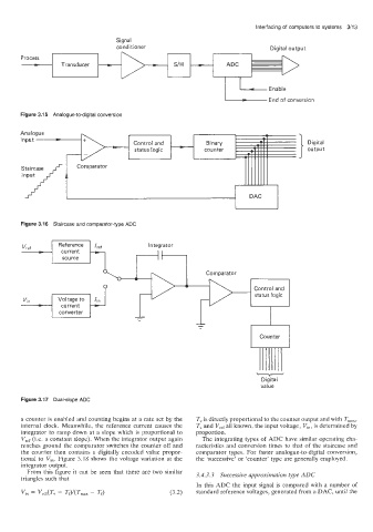
Interfacing of  computers to systems  3/13
                                Signal
                                conditioner                              Digital output
                                                             -
       Process


       Figure 3.11 5  Analogue-to-digital conversion                     End  of  conversion


      Analogue
       input -
                                                                                   Digital
                                                                                   output
       Staircase
       input
          i


       Figure 3:16   Staircase and comparator-type ADC
       -                                 Integrator
       Vref


                                                                     v
                                                                       Digital
                                                                       value
       Figure 3.117  Dual-slope ADC

       a counter is enabled and counting begins at a rate set by  the   T, is directly proportional to the counter output and with T,,,,,,
       internal clock.  Meanwhile,  the  reference  current causes  the   T, and Vref all known, the input voltage, Vi,,  is determined by
       integrator to ramp down at a slope which is proportional  to   proportion.
       Vref (Le. a constant slope). When the integrator output again   The integrating types of  ADC have similar operating cha-
       reaches  ground  the comparator switches the counter off  and   racteristics  and conversion times  to that of  the staircase and
       the  counter  then contains  a  digitally encoded  value  propor-   comparator types.  For faster  analogue-to-digital conversion,
       tional  to VI".  Figure  3.18 shows thie  voltage variation  at the   the 'successive'  or 'counter'  type are generally  employed.
       integrator output.
        From this figure it  can  be  seen that  there  are two  similar   3.4.3.3  Successive approximation type ADC
       triangles such that
                                                     In this ADC the input signal is compared  with  a number of
                                                     standard reference voltages, generated from a DAC, until the