
Page 128 - Mechanical Engineers Reference Book
P. 128
interfacing of computers to systems 311 1
implemented over the remainder of the sync pulse. Two
separate timing loops are used to control the MARK and
SPACE times, respectively. Due to the relatively high fre-
quency of the output signal, the control software must be
written in assembly language for speed. An alternative to this
is to use hardware support chips to output the PWM signal
under the control of the computer’s CPU.
t 11 .nA
3.4.2.3 Controlling a.c. power by control of thyristor phase
angle
Various applications, such as temperature control, require a.c.
power adjustment and solid-state relays can be used effectively
to vary output power between 0% and 100%. The power is
controlled by varying the phase angle between the supply
voltage and that which appears across the load when current
conduction begins. A phase control device operating off a
&5 V signal from a DAC can be used to alter the phase angle
between voltage and current in the range &180”. The control
of the power output to the load is non-linear. but linearization
between output and input can be accomplished in the soft-
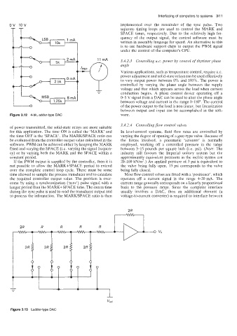
Figure 31.12 4-bit, adder-type DAC ware.
3.4.2.4 Controlling flow control valves
of power transmitted, the solid-state relays are more suitable
for this application. The time ON is called the ‘MARK’ and In level-control systems, fluid flow rates are controlled by
the time OFF is the ‘SPACE’. The MARWSPACE ratio can varying the degree of opening of a gate-type vaive. Because of
be evaluated from the controller output value calculated in the the forces involved, a pneumatic ‘actuator’ is normally
software. PWM can be achieved either by keeping the MARK employed, working off a controlled pressure in the range
fixed and varying the SPACE (Le. varying the signal frequen- between 3-15 pounds per square inch (Le. psi). (Note: The
cy) or by varying both the MARK and the SPACE within a industry still favours the Imperial unitary system hut the
constant period. approximatel e uivalent pressures in the metric system are
7s
If the PWM output is supplied by the controller, then it is 20-100 kNim-.) An applied pressure of 3 psi is equivalent to
not possible to allow the MARK+SPACE period to extend the valve being fully open, 15 psi corresponds to the valve
over the complete control loop cycle. There must be some being fully closed.
time allowed to sample the process transducer and to calculate Most flow control valves are fitted with a ‘positioner‘, which
the required controller output value. The problem is over- operates off a current signal in the range 4-20 mA. The
come by using a synchronization (‘sync’) pulse signal with a current range generally corresponds on a linearly proportional
longer period than the MARK+SPACE time. The excess time basis to the pressure range. Since the computer interface
during the sync pulse is used to read the transducer output and usually involves a DAC, then an additional element (a
to process the information. The MARWSPACE ratio is then voltage-to-current converter) is required to interface between
Figure 3.13 Ladder-type DAC