
Page 142 - Mechanical Engineers Reference Book
P. 142
Instrumentation 3/25
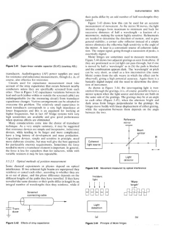
their paths differ by an odd number of half wavelengths they
cancel.
Figure 3.43 shows how this can be used for an accurate
measurement of movement. As the mirror M moves, the light
intensity changes from maximum to minimum and back for
successive distances of half a wavelength - a fraction of a
micrometre, making the system highly sensitive. Refinements
are needed to determine the direction of motion, and to give
general stability; a corner cube reflector instead of a simple
mirror eliminates the otherwise high sensitivity to the angle of
the mirror. A laser is a convenient source of coherent radia-
tion. The output signal, going through a succession of peaks, is
essentially digital.
Moire fringes are sometimes used to measure movement.
Figure 3.44 shows two adjacent gratings as seen from above. If
they are positioned as in (a) light can pass through, but if one
Figure 3.41 Super-linear variable capacitor (SLVC) (courtesy ASL) is moved by half a 'wavelength' as in (b) the path is blocked
and the combination appears dark. The 'wavelength' or pitch
can be very short, as small as a few micrometres (the name
transducers. Audiofrequency (AF) power supplies are used
for resistance and inductance measurements, though d.c. is, of Moire comes from the silk weave in which the effect can be
course, also effective for resistance. observed), giving a high potential accuracy. Again there is a
Circuits used for capacitance measurement must take basically digital output and the need to determine the direc-
account of the stray capacitance that occurs between nearby tion of movement.
conductors unless they are specifically screened from each As shown in Figure 3.44, the interrogating light is tran-
other. Thus in Figure 3.42 capacitance variations between its smitted through the gratings; it is, of course, possible to have a
mirror system when the light source and detector are both on
lead and earth (either within or outside the screened cable) are
indistinguishable (to the measuring circuit) from transducer the same side of the gratings. The gratings may be at an angle
capacitance changes. Various arrangements can be adopted to to each other (Figure 3.49, when the alternate bright and
overcome this problem. The relatively small capactiance in dark areas form fringes perpendicular to the gratings; the
most transducers corresponds to a very high impedance at fringes move bodily with linear displacement of either grating,
lower frequencies and this is an argument for working at while the separation between them depends on the angle
higher frequencies, but in fact AF bridge systems with very between the two.
high sensitivities are available and give good performance
when spurious effects are eliminated. Reference
Many considerations come into the choice of transducer mirror
technique. As a very simple summary, it may be suggested
that resistance devices are simple and inexpensive, inductance
devices, while tending to be larger and more complicated,
have a long history of development and mass production.
M
Capacitance devices, simple and sensitive in principle, need 1 1 I I / / M
Coherent
more elaborate circuitry, but may well give the best approach Coherent - - - - - -
/
for particualrly onerous requirements. Sometimes the force light source /
light
source
needed to move a transducer element is important. In general,
the force is less for capacitors than for inductors, while with
variable resistors it may be less repeatable.
Light
3.5.2.5 Optical methods of position measurement detector
Some classical experiments in physics depend on optical
interference. If two coherent light beams are superposed they Figure 3.43 Movement measured by optical interference
reinforce or cancel each other, according to whether they are
in or out of phase, and this phase difference depends on the Incident
different lengths of the paths they have travelled. If they have light
travelled the same distance or their paths differ in length by an 'Wave-
integral number of wavelengths then they reinforce, while if 1111 length'
A
0 0'0'0'0 ooboo
Screened 00000 00000
connectinq cable
Light
detection
&
(a) (b)
Figure 3.42 Effects of stray capacitance Figure 3.44 Principle of Moir6 fringes