
Page 143 - Mechanical Engineers Reference Book
P. 143
3/26 Microprocessors, instrumentation and control
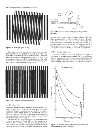
Pressure
gauge
Air supply
Restrictor Flapper
Nozzle
Figure 3.47 Pneumatic nozzle and flapper (courtesy Foxboro
Company)
re P just upstream of the nozzle is shown in Figure 3.48. The
effect can be amplified by the introduction of further elements
in the shape of valves and a pressure-sensitive diaphragm. The
primary behaviour is inherently non-linear, but the use of a
pressure-feedback device with levers and a spring-controlled
bellows allows a movement of the order of a millimetre to give
Figure 3.45 Moire gratings at an angle a proportional pressure change of some tens of kilopascals.
If the gratings do not have quite the same pitch, there are 3.5.2.7 Angular displacement
fringes parallel to the grating elements (Figure 3.46). This The synchro - sometimes called a Magslip or Selsyn - is
principle is sometimes used in strain measurement, when the widely used in the measurement of angles. If ax. is applied to
strain to be measured is arranged to alter the pitch. In all these the central element [rotor) of such a device (left-hand side of
arrangements there is an effective magnification, so that small Figure 3.49) then the voltages induced in the three circumfe-
movements, on the scale of the small pitch of the gratings, give rential windings depend on the angular position of the rotor
rise to much larger movements of the fringes.
Air supply pressure
120
100
80
I
m
a
YI
E
60
E
n
._
L
Q
Figure 3.46 Unequally spaced Moire gratings
40
3.5.2.6 Pneumatics
Currently, pneumatic instrumentation systems are used less
than electronic ones. They have the drawbacks of needing 20
somewhat delicate mechanical devices and of introducing
significant delays when signals are transmitted over long
distances. However, they are by no means extinct and have
c
the great safety advantage that there need be no question of -
0
their introducing electric sparks. 0 I I I
The heart of a pneumatic instrument is a flapper adjacent to 0.2 0.4 0.6
a nozzle as shown in Figure 3.47. As the separation, d, Distanced (mm)
between these is changed, the air flow through the nozzle
changes markedly and hence also the pressure drop across the Figure 3.48 Relation between pressure and gap for pneumatic
‘series’ restrictor. A typical relation between d and the pressu- device (courtesy of Foxboro Company)