
Page 138 - Mechanical Engineers Reference Book
P. 138
Instrumentation 3/21
R 3.5 Instrumentation
3.5.1 Introduction
Many aspects of mechanical engineering depend essentially on
the ability to make measurements of relevant quantities. In
some areas, such as non-destructive testing or experimental
stress analysis, the techniques for making the measurements
are linked so closely to the rest of the subject that they are
better dealt with in their particular context. Here, we consider
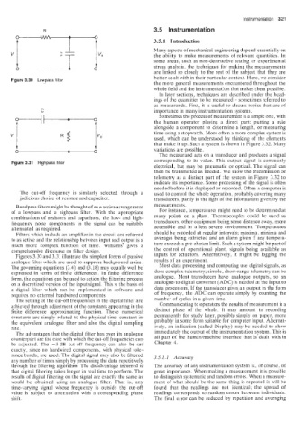
Figure 3.30 Lowpass filter
the more general measurements encountered throughout the
whole field and the instrumentation that makes them possible.
In later sections, techniques are described under the head-
ings of the quantities to be measured - sometimes referred to
as measurands. First, it is useful to discuss topics that are of
C importance in many instrumentation systems.
Sometimes the process of measurement is a simple one, with
the human operator playing a direct part: putting a rule
alongside a component to determine a length, or measuring
time using a stopwatch. More often a more complex system is
used, which can be understood by thinking of the elements
- that make it up. Such a system is shown in Figure 3.32. Many
variations are possible.
0 A 0
The measurand acts on a transducer and produces a signal
Figure 3.31 Highpass filter corresponding to its value. This output signal is commonly
electrical, but may be pneumatic or optical. The signal can
then be transmitted as needed. We show the transmission or
telemetry as a distinct part of the system in Figure 3.32 to
indicate its importance. Some processing of the signai is often
needed before it is displayed or recorded. Often a computer is
The cut-off frequency is similarly selected through a used to control the whole operation. probably covering many
judicious choice of resistor and capacitor. transducers, partly in the light of the information given by the
Bandpass filters might be thought of as a series arrangement measurements.
of a lowpass and a highpass filter. With the appropriate For instance. temperatures might need to be determined at
combinations of resistors and capacitors, the low- and high- many points on a plant. Thermocouples could be used as
frequency noise components in the signal can be suitably transducers, other equipment being some distance away, more
attenuated as required. accessible and in a less severe environment. Temper- dura
Filters which include an amplifier in the circuit are referred should be recorded at regular intervals; maxima, minima and
bo as active and the relationship between input and output is a averages being extracted and an alarm given if any tempera-
much more complex function of time. Williams7 gives a ture exceeds a pre-chosen limit. Such a system might be part of
comprehensive discourse on filter design. the control of operational plant, signals being available as
Figures 3.30 and 3.31 illustrate the simplest forms of passive inputs for actuators. Alternatively, it might be logging the
analogue filter which are used to suppress background noise. results of an experiment.
The governing equations (3.4) and (3.18) may equally well be Most data processing and computing use digital signals. as
expressed in terms of finite differences. In finite difference does complex telemetry; simple, short-range telemetry can he
form, the equations can be used to action the fiitering process analogue. Most transducers have analogue outputs, so an
on a discretized version of the input signal. This is the basis of analogue-to-digital converter (ADC) is needed at the input to
a digital filter which can be implemented in software and data processors. If the transducer gives an output in the form
requires no external hardwired components. of frequency, the ADC can operate simply by counting the
The setting of the cut-off frequencies in the digital filter are number of cycles in a given time.
achieved through adjustment of the constants appearing in the Communicating to operators the results of measurement is a
finite difference approximating function. These numerical distinct phase of the whole. It may amount to recording
constants are simply related to the physical time constant in permanently for study later, possibly simply on paper, more
the equivalent analogue filter and also the digital sampling probably in some form suitable for computer input. Alternat-
rate. ively, an indication (called Display) may be needed to show
The advantages that the digital filter has over its analogue immediately the output of the instrumentation system. This is
counterpart are the ease with which the cut-off frequencies can all part of the humanhachine interface that is dealt with in
be adjusted. The -3 dB cut-off frequency can also be set Chapter 4.
exactly, since no hardwired components, with physical tole-
rance bands, are used. The digital signal may also be filtered 3.5.1.1 Accuracy
any number of times simply by processing the data repetitively
through the filtering algorithm. The disadvantage incurred is The accuracy of any instrumentation system is, of course, of
that digitai filtering takes longer in real time to perform. The great importance. When making a measurement it is possible
results of digital filtering on the signal are exactly the same as to distinguish systematic and random errors. When a measure-
would be obtained using an analogue filter. That is, any ment of what should be the same thing is repeated it will be
time-varying signal whose frequency is outside the cut-off found that the readings are not identical; the spread of
value is subject to atteeuation with a corresponding phase readings corresponds to random errors between individuals.
shift. The final error can be reduced by repetition and averaging