
Page 337 - Mechanical Engineers' Handbook (Volume 2)
P. 337
328 Mathematical Models of Dynamic Physical Systems
In words, the zero-state output corresponding to an arbitrary input u(t) can be determined
by convolution with the impulse response h(t). In other words, the impulse response com-
pletely characterizes the system. The impulse response is also called the system weighing
function.
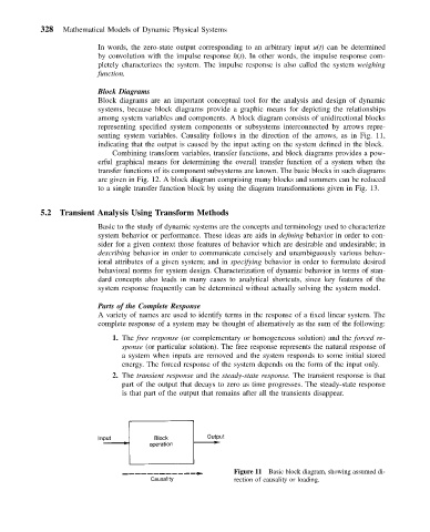
Block Diagrams
Block diagrams are an important conceptual tool for the analysis and design of dynamic
systems, because block diagrams provide a graphic means for depicting the relationships
among system variables and components. A block diagram consists of unidirectional blocks
representing specified system components or subsystems interconnected by arrows repre-
senting system variables. Causality follows in the direction of the arrows, as in Fig. 11,
indicating that the output is caused by the input acting on the system defined in the block.
Combining transform variables, transfer functions, and block diagrams provides a pow-
erful graphical means for determining the overall transfer function of a system when the
transfer functions of its component subsystems are known. The basic blocks in such diagrams
are given in Fig. 12. A block diagram comprising many blocks and summers can be reduced
to a single transfer function block by using the diagram transformations given in Fig. 13.
5.2 Transient Analysis Using Transform Methods
Basic to the study of dynamic systems are the concepts and terminology used to characterize
system behavior or performance. These ideas are aids in defining behavior in order to con-
sider for a given context those features of behavior which are desirable and undesirable; in
describing behavior in order to communicate concisely and unambiguously various behav-
ioral attributes of a given system; and in specifying behavior in order to formulate desired
behavioral norms for system design. Characterization of dynamic behavior in terms of stan-
dard concepts also leads in many cases to analytical shortcuts, since key features of the
system response frequently can be determined without actually solving the system model.
Parts of the Complete Response
A variety of names are used to identify terms in the response of a fixed linear system. The
complete response of a system may be thought of alternatively as the sum of the following:
1. The free response (or complementary or homogeneous solution) and the forced re-
sponse (or particular solution). The free response represents the natural response of
a system when inputs are removed and the system responds to some initial stored
energy. The forced response of the system depends on the form of the input only.
2. The transient response and the steady-state response. The transient response is that
part of the output that decays to zero as time progresses. The steady-state response
is that part of the output that remains after all the transients disappear.
Figure 11 Basic block diagram, showing assumed di-
rection of causality or loading.