Page 430 - Mechanical Engineers' Handbook (Volume 2)
P. 430
9 Graphical Design Methods  421

                           for the gain and phase margins are satisfied. If I action or D action is included, the propor-
                           tional gain is selected last. Therefore, when using this approach to the design, it is best to
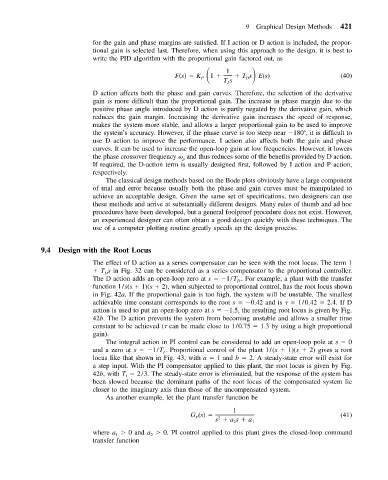
                           write the PID algorithm with the proportional gain factored out, as
                                                  F(s)   K      1    Ts E(s)
                                                           1
                                                         P
                                                               Ts    D                          (40)
                                                                I
                           D action affects both the phase and gain curves. Therefore, the selection of the derivative
                           gain is more difficult than the proportional gain. The increase in phase margin due to the
                           positive phase angle introduced by D action is partly negated by the derivative gain, which
                           reduces the gain margin. Increasing the derivative gain increases the speed of response,
                           makes the system more stable, and allows a larger proportional gain to be used to improve
                           the system’s accuracy. However, if the phase curve is too steep near  180 , it is difficult to
                           use D action to improve the performance. I action also affects both the gain and phase
                           curves. It can be used to increase the open-loop gain at low frequencies. However, it lowers
                           the phase crossover frequency   and thus reduces some of the benefits provided by D action.
                                                    p
                           If required, the D-action term is usually designed first, followed by I action and P action,
                           respectively.
                              The classical design methods based on the Bode plots obviously have a large component
                           of trial and error because usually both the phase and gain curves must be manipulated to
                           achieve an acceptable design. Given the same set of specifications, two designers can use
                           these methods and arrive at substantially different designs. Many rules of thumb and ad hoc
                           procedures have been developed, but a general foolproof procedure does not exist. However,
                           an experienced designer can often obtain a good design quickly with these techniques. The
                           use of a computer plotting routine greatly speeds up the design process.


            9.4  Design with the Root Locus
                           The effect of D action as a series compensator can be seen with the root locus. The term 1
                             T s in Fig. 32 can be considered as a series compensator to the proportional controller.
                              D
                           The D action adds an open-loop zero at s   1/T . For example, a plant with the transfer
                                                                   D
                           function 1/s(s   1)(s   2), when subjected to proportional control, has the root locus shown
                           in Fig. 42a. If the proportional gain is too high, the system will be unstable. The smallest
                           achievable time constant corresponds to the root s   0.42 and is     1/0.42   2.4. If D
                           action is used to put an open-loop zero at s   1.5, the resulting root locus is given by Fig.
                           42b. The D action prevents the system from becoming unstable and allows a smaller time
                           constant to be achieved (  can be made close to 1/0.75   1.3 by using a high proportional
                           gain).
                              The integral action in PI control can be considered to add an open-loop pole at s   0
                           and a zero at s   1/T . Proportional control of the plant 1/(s   1)(s   2) gives a root
                                              I
                           locus like that shown in Fig. 43, with a   1 and b   2. A steady-state error will exist for
                           a step input. With the PI compensator applied to this plant, the root locus is given by Fig.
                           42b, with T   2/3. The steady-state error is eliminated, but the response of the system has
                                    I
                           been slowed because the dominant paths of the root locus of the compensated system lie
                           closer to the imaginary axis than those of the uncompensated system.
                              As another example, let the plant transfer function be

                                                                  1
                                                      G (s)                                     (41)
                                                       P
                                                              2
                                                             s   as   a 1
                                                                  2
                           where a   0 and a   0. PI control applied to this plant gives the closed-loop command
                                 1
                                           2
                           transfer function

