Page 559 - Mechanical Engineers' Handbook (Volume 2)
P. 559
550   Servoactuators for Closed-Loop Control

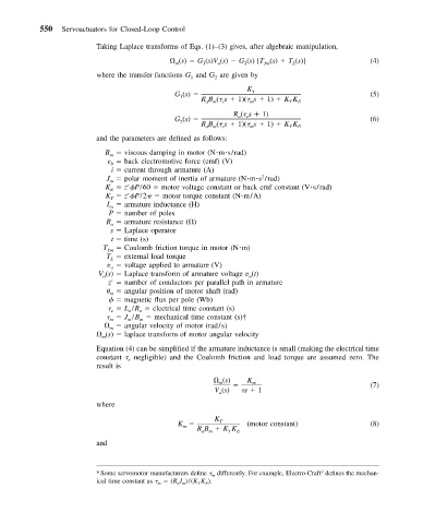
                          Taking Laplace transforms of Eqs. (1)–(3) gives, after algebraic manipulation,
                                              (s)   G (s)V (s)   G (s)[T (s)   T (s)]          (4)
                                              m
                                                               2
                                                         a
                                                                    ƒm
                                                                            L
                                                     1
                          where the transfer functions G and G are given by
                                                  1
                                                        2
                                                                K
                                              G (s)              T                             (5)
                                               1
                                                    RB (  s   1)(  s   1)   KK E
                                                                           T
                                                          e
                                                     am
                                                                 m
                                                             R (  s   1)
                                              G (s)           a  e                             (6)
                                               2
                                                    RB (  s   1)(  s   1)   KK
                                                     am   e      m         T  E
                          and the parameters are defined as follows:
                            B   viscous damping in motor (N m s/rad)
                             m
                            e   back electromotive force (emf) (V)
                             b
                             i   current through armature (A)
                            J   polar moment of inertia of armature (N m s /rad)
                                                                    2
                             m
                            K   z  P/60   motor voltage constant or back emf constant (V s/rad)
                             E
                            K   z  P/2    motor torque constant (N m/A)
                             T
                            L   armature inductance (H)
                             a
                             P   number of poles
                            R   armature resistance ( )
                             a
                             s   Laplace operator
                             t   time (s)
                           T ƒm    Coulomb friction torque in motor (N m)
                            T   external load torque
                             L
                            v   voltage applied to armature (V)
                             a
                          V (s)   Laplace transform of armature voltage v (t)
                           a
                                                                a
                             z    number of conductors per parallel path in armature
                                angular position of motor shaft (rad)
                             m
                                 magnetic flux per pole (Wb)
                                 L /R   electrical time constant (s)
                                     a
                                  a
                             e
                                J /B   mechanical time constant (s)†
                             m
                                     m
                                  m
                                angular velocity of motor (rad/s)
                             m
                            (s)   laplace transform of motor angular velocity
                           m
                          Equation (4) can be simplified if the armature inductance is small (making the electrical time
                          constant   negligible) and the Coulomb friction and load torque are assumed zero. The
                                  e
                          result is
                                                         (s)     K m                           (7)
                                                         m
                                                        V (s)   s   1
                                                         a
                          where
                                                        K
                                              K          T      (motor constant)               (8)
                                                m
                                                   RB   KK   E
                                                    am
                                                           T
                          and
                                                                                   9
                          *Some servomotor manufacturers define   m differently. For example, Electro-Craft defines the mechan-
                          ical time constant as   m   (R a J m )/(K T K E ).

