Page 561 - Mechanical Engineers' Handbook (Volume 2)
P. 561
552   Servoactuators for Closed-Loop Control

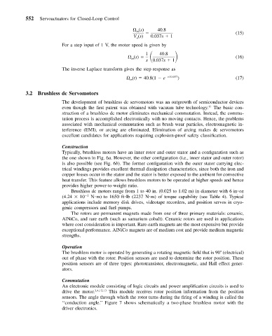
                                                        (s)     40.8                          (15)
                                                       m
                                                      V (s)  0.037s   1
                                                       a
                          For a step input of 1 V, the motor speed is given by
                                                      (s)       40.8
                                                           1
                                                     m
                                                           s  0.037s   1                      (16)
                          The inverse Laplace transform gives the step response as
                                                     (t)   40.8(1   e  t /0.037 )             (17)
                                                     m

           3.2  Brushless dc Servomotors
                          The development of brushless dc servomotors was an outgrowth of semiconductor devices
                          even though the first patent was obtained with vacuum tube technology. 11  The basic con-
                          struction of a brushless dc motor eliminates mechanical commutation. Instead, the commu-
                          tation process is accomplished electronically with no moving contacts. Hence, the problems
                          associated with mechanical commutation such as brush wear particles, electromagnetic in-
                          terference (EMI), or arcing are eliminated. Elimination of arcing makes dc servomotors
                          excellent candidates for applications requiring explosion-proof safety classification.

                          Construction
                          Typically, brushless motors have an inner rotor and outer stator and a configuration such as
                          the one shown in Fig. 6a. However, the other configuration (i.e., inner stator and outer rotor)
                          is also possible (see Fig. 6b). The former configuration with the outer stator carrying elec-
                          trical windings provides excellent thermal dissipation characteristics, since both the iron and
                          copper losses occur in the stator and the stator is better exposed to the ambient for convective
                          heat transfer. This feature allows brushless motors to be operated at higher speeds and hence
                          provides higher power-to-weight ratio.
                             Brushless dc motors range from 1 to 40 in. (0.025 to 1.02 m) in diameter with 6 in oz
                          (4.24   10  2  N m) to 1650 ft lb (2237 N m) of torque capability (see Table 4). Typical
                          applications include memory disk drives, videotape recorders, and position servos in cryo-
                          genic compressors and fuel pumps.
                             The rotors are permanent magnets made from one of three primary materials: ceramic,
                          AlNiCo, and rare earth (such as samarium cobalt). Ceramic rotors are used in applications
                          where cost consideration is important. Rare-earth magnets are the most expensive but provide
                          exceptional performance. AlNiCo magnets are of medium cost and provide medium magnetic
                          strengths.

                          Operation
                          The brushless motor is operated by generating a rotating magnetic field that is 90  (electrical)
                          out of phase with the rotor. Position sensors are used to determine the rotor position. These
                          position sensors are of three types: phototransistor, electromagnetic, and Hall effect gener-
                          ators.

                          Commutation
                          An electronic module consisting of logic circuits and power amplification circuits is used to
                          drive the motor. 3,4,12,13  This module receives rotor position information from the position
                          sensors. The angle through which the rotor turns during the firing of a winding is called the
                          ‘‘conduction angle.’’ Figure 7 shows schematically a two-phase brushless motor with the
                          driver electronics.

