
Page 564 - Mechanical Engineers' Handbook (Volume 2)
P. 564
3 Direct-Current Servomotors 555
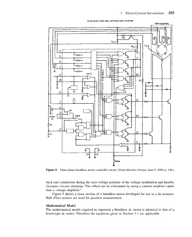
Figure 8 Three-phase brushless motor controller circuit. (From Machine Design, June 9, 1988, p. 140.)
back-emf conduction during the zero-voltage portions of the voltage modulation and thereby
increases viscous damping. This effect can be eliminated by using a current amplifier rather
than a voltage amplifier. 9
Figure 9 shows a cross section of a brushless motor developed for use as a fin actuator.
Hall effect sensors are used for position measurement.
Mathematical Model
The mathematical model required to represent a brushless dc motor is identical to that of a
brush-type dc motor. Therefore the equations given in Section 3.1 are applicable.