
Page 563 - Mechanical Engineers' Handbook (Volume 2)
P. 563
554 Servoactuators for Closed-Loop Control
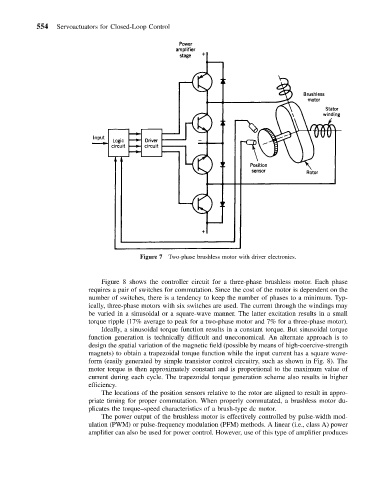
Figure 7 Two-phase brushless motor with driver electronics.
Figure 8 shows the controller circuit for a three-phase brushless motor. Each phase
requires a pair of switches for commutation. Since the cost of the motor is dependent on the
number of switches, there is a tendency to keep the number of phases to a minimum. Typ-
ically, three-phase motors with six switches are used. The current through the windings may
be varied in a sinusoidal or a square-wave manner. The latter excitation results in a small
torque ripple (17% average to peak for a two-phase motor and 7% for a three-phase motor).
Ideally, a sinusoidal torque function results in a constant torque. But sinusoidal torque
function generation is technically difficult and uneconomical. An alternate approach is to
design the spatial variation of the magnetic field (possible by means of high-coercive-strength
magnets) to obtain a trapezoidal torque function while the input current has a square wave-
form (easily generated by simple transistor control circuitry, such as shown in Fig. 8). The
motor torque is then approximately constant and is proportional to the maximum value of
current during each cycle. The trapezoidal torque generation scheme also results in higher
efficiency.
The locations of the position sensors relative to the rotor are aligned to result in appro-
priate timing for proper commutation. When properly commutated, a brushless motor du-
plicates the torque–speed characteristics of a brush-type dc motor.
The power output of the brushless motor is effectively controlled by pulse-width mod-
ulation (PWM) or pulse-frequency modulation (PFM) methods. A linear (i.e., class A) power
amplifier can also be used for power control. However, use of this type of amplifier produces