Page 568 - Mechanical Engineers' Handbook (Volume 2)
P. 568

4 Alternating-Current Servomotors  559

                           to-inertia ratio is improved by the use of drag-cup construction (see Fig. 11c). The efficiency
                           of ac servomotors is fairly low (5–20%), which necessitates external cooling.


            4.2 Mathematical Model
                           Steady-State Model
                           Assuming linearity (i.e., operation without magnetic saturation) and using the method of
                           symmetrical components, 18  mathematical models can be developed for the ac servomotor.
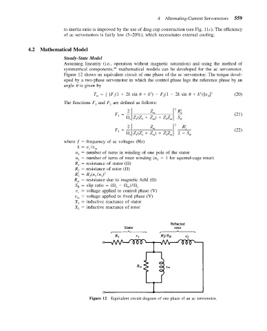
                           Figure 12 shows an equivalent circuit of one phase of the ac servomotor. The torque devel-
                           oped by a two-phase servomotor in which the control phase lags the reference phase by an
                           angle   is given by
                                       T    – [F (1   2k sin     k )   F (1   2k sin     k )] v   2  (20)
                                            1
                                                              2
                                                                                  2
                                        m   4  1                   2                 m
                           The functions F and F are defined as follows:
                                       1
                                             2
                                               F              Z m        2  R  2
                                                    2
                                                 1
                                                      Z (Z   Z )   ZZ    S R                    (21)
                                                     s
                                                          2
                                                               m
                                                                    2 m
                                                        1
                                               F              Z m        2  R  2
                                                    2
                                                 2                                              (22)
                                                      Z (Z    Z )   Z Z  2   S R
                                                          2
                                                               m
                                                                    2 m
                                                     s
                                                        1
                           where ƒ   frequency of ac voltages (Hz)
                                k   v /v m
                                     c
                                n   number of turns in winding of one pole of the stator
                                1
                                n   number of turns of rotor winding (n   1 for squirrel-cage rotor)
                                                                2
                                2
                               R   resistance of stator ( )
                                1
                               R   resistance of rotor ( )
                                2
                               R  2    R (n /n ) 2
                                       1
                                          2
                                     2
                               R   resistance due to magnetic field ( )
                                m
                               S   slip ratio   (      )/  s
                                R
                                                s
                                                    m
                                v   voltage applied to control phase (V)
                                 c
                               v   voltage applied to fixed phase (V)
                                m
                               X 1   inductive reactance of stator
                               X   inductive reactance of rotor
                                2
                                     Figure 12 Equivalent circuit diagram of one phase of an ac servomotor.
   563   564   565   566   567   568   569   570   571   572   573