
Page 570 - Mechanical Engineers' Handbook (Volume 2)
P. 570
4 Alternating-Current Servomotors 561
1
A v T m (23)
m
c
B
where
A m (24)
v c
1
m
(25)
B
T m
The symbol indicates small variations from the steady-state operating point. Including the
electrical and mechanical dynamics gives the transfer function
A V (s) (1/B) T (s)
(s) c m (26)
m
( s 1)( s 1)
m
e
where B damping coefficient of motor (N m s)
m
J polar moment of inertia of rotor (N m s /rad)
2
m
L inductance of stator (H)
1
R resistance of stator ( )
1
s Laplace variable
T change in load torque reflected to motor shaft
m
T (s) Laplace transform of change in load torque reflected to motor shaft
m
L /R electrical time constant (s)
e
1
1
J /B mechanical time constant (s)
m
m
m
(s) Laplace transform of change in motor speed
m
Computation of the constants A and B of Eq. (26) from the torque expression of Eq.
(20) is rather tedious and requires measurements of the rotor impedances over a speed range
of to . As an alternative, an approximate expression for the torque has been de-
s s
veloped 18 as follows:
T S R (27)
m
C CS 2
1 2 R
where C and C are constants which are determined from two points on an experimentally
2
1
measured torque–speed characteristic. The constants A and B in Eq. (23) are related to C 1
and C as follows:
2
2 (C C )
A s 1 2 sin (28)
v m (C C )
2
1
1(C C )
B 1 2 (29)
2 (C C ) 2
1
2
s
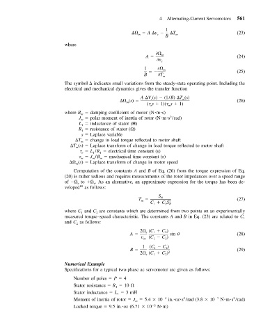
Numerical Example
Specifications for a typical two-phase ac servomotor are given as follows:
Number of poles P 4
Stator resistance R 10
1
Stator inductance L 3mH
1
2
2
Moment of inertia of rotor J 5.4 10 5 in. oz s /rad (3.8 10 7 N m s /rad)
m
Locked torque 9.5 in. oz (6.71 10 2 N m)