
Page 572 - Mechanical Engineers' Handbook (Volume 2)
P. 572
5 Stepper Motors 563
advantage of stepper motors is their low efficiency, which restricts their use to fractional
horsepower applications.
5.1 Operation
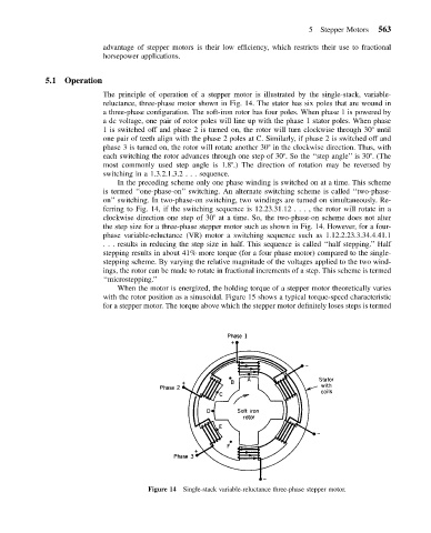
The principle of operation of a stepper motor is illustrated by the single-stack, variable-
reluctance, three-phase motor shown in Fig. 14. The stator has six poles that are wound in
a three-phase configuration. The soft-iron rotor has four poles. When phase 1 is powered by
a dc voltage, one pair of rotor poles will line up with the phase 1 stator poles. When phase
1 is switched off and phase 2 is turned on, the rotor will turn clockwise through 30 until
one pair of teeth align with the phase 2 poles at C. Similarly, if phase 2 is switched off and
phase 3 is turned on, the rotor will rotate another 30 in the clockwise direction. Thus, with
each switching the rotor advances through one step of 30 . So the ‘‘step angle’’ is 30 . (The
most commonly used step angle is 1.8 .) The direction of rotation may be reversed by
switching in a 1.3.2.1.3.2... sequence.
In the preceding scheme only one phase winding is switched on at a time. This scheme
is termed ‘‘one-phase-on’’ switching. An alternate switching scheme is called ‘‘two-phase-
on’’ switching. In two-phase-on switching, two windings are turned on simultaneously. Re-
ferring to Fig. 14, if the switching sequence is 12.23.31.12 ...,the rotor will rotate in a
clockwise direction one step of 30 at a time. So, the two-phase-on scheme does not alter
the step size for a three-phase stepper motor such as shown in Fig. 14. However, for a four-
phase variable-reluctance (VR) motor a switching sequence such as 1.12.2.23.3.34.4.41.1
. . . results in reducing the step size in half. This sequence is called ‘‘half stepping.’’ Half
stepping results in about 41% more torque (for a four phase motor) compared to the single-
stepping scheme. By varying the relative magnitude of the voltages applied to the two wind-
ings, the rotor can be made to rotate in fractional increments of a step. This scheme is termed
‘‘microstepping.’’
When the motor is energized, the holding torque of a stepper motor theoretically varies
with the rotor position as a sinusoidal. Figure 15 shows a typical torque-speed characteristic
for a stepper motor. The torque above which the stepper motor definitely loses steps is termed
Figure 14 Single-stack variable-reluctance three-phase stepper motor.