
Page 573 - Mechanical Engineers' Handbook (Volume 2)
P. 573
564 Servoactuators for Closed-Loop Control
Figure 15 Typical relation between pull-in
torque and pull-out torque of a stepper motor.
(From B.C. Kuo, Incremental Motion Control-
Step Motors and Control Systems, Vol. II, SRL
Publishing, Champaign, IL, 1979, p. 101).
the ‘‘pull-out torque.’’ The torque below which a stepper does not lose any steps (in an open-
loop mode) is termed the ‘‘pull-in torque.’’ The speed range between the pull-in and pull-
out torques is called the ‘‘slew range.’’ The slew range represents an unstable region of
operation.
5.2 Types of Stepper Motors
In the early years of stepper motor development, stepper design included mechanical de-
tenting and solenoid controls. However, these designs have been replaced by more rugged
19
and efficient designs. The latter designs may be broadly classified as (1) permanent-magnet
steppers, (2) variable-reluctance steppers, (3) hybrid steppers, (4) electromechanical steppers,
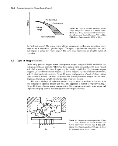
and (5) electrohydraulic steppers. Figure 16 shows configurations of each of these various
types of stepper motors. The most commonly used are the permanent-magnet and the three-
phase and four-phase variable-reluctance types of stepper motors.
The stator windings of variable-reluctance stepper motors sometimes are wound with
two windings of opposite polarity per pole. This approach is termed a ‘‘bipolar winding.’’
Figure 17 shows a bipolar-wound stepper motor. This arrangement provides more torque and
improves damping, but the disadvantage is more complex circuitry.
Figure 16 Stepper motor configurations. (From
B. C. Kuo, Incremental Motion Control-Step
Motors and Control Systems, Vol. II, SRL Pub-
lishing Co., Champaign, IL, 1979, pp. 12–14.):
(a) permanent stator stepper motor.