Page 569 - Mechanical Engineers' Handbook (Volume 2)
P. 569
560   Servoactuators for Closed-Loop Control

                              X  2    X (n /n ) 2
                                      1
                                    2
                                         2
                              X   inductive reactance due to magnetic field
                               m
                              Z   stator impedance   R   jX 1
                               1
                                                    1
                              Z   reflected impedance of rotor at S   (R  2 /S )   jX  2
                                                             R
                                                                     R
                               2
                              Z  2    reflected impedance of rotor at (2   S )   R  2 /(2   S )   jX  2
                                                                             R
                                                                 R
                              Z   impedance due to magnetic field generation in the stator   [(1/R )   (1/jX )]  1
                               m
                                                                                      m
                                                                                              m
                                   phase angle between fixed and control voltages
                                  motor speed (rad/s)
                               m
                                  synchronous speed (rad/s)
                               s
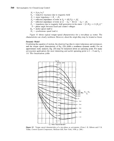
                             Figure 13 shows typical torque–speed characteristics for a two-phase ac motor. The
                          characteristics are clearly nonlinear. However, about the origin they may be treated as linear.
                          Dynamic Model
                          Combining the equation of motion, the electrical lag (due to stator inductance and resistance),
                          and the torque–speed characteristic of Eq. (20) yields a nonlinear dynamic model. For an
                          approximate static analysis, Eq. (20) may be linearized about an operating point. For many
                          servosystem applications the most interesting and useful operating point is k   0 and S
                                                                                               R
                          1.0. This linearization yields


                          Figure 13 Torque–speed characteristics of a two-phase ac servomotor. (From J. E. Gibson and F. B.
                          Tueter, Control System Components, McGraw-Hill, New York, 1958, p. 288.)

