Page 560 - Mechanical Engineers' Handbook (Volume 2)
P. 560
3 Direct-Current Servomotors  551

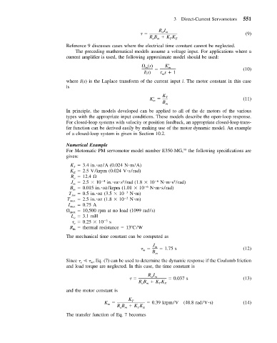
                                                               RJ
                                                                am                               (9)
                                                           RB   KK   E
                                                            am
                                                                   T
                           Reference 9 discusses cases where the electrical time constant cannot be neglected.
                              The preceding mathematical models assume a voltage input. For applications where a
                           current amplifier is used, the following approximate model should be used:
                                                          (s)     K  m                          (10)
                                                          m
                                                         I(s)    s   1
                                                                m
                           where I(s) is the Laplace transform of the current input i. The motor constant in this case
                           is

                                                           K     K T                            (11)
                                                             m
                                                                B m
                           In principle, the models developed can be applied to all of the dc motors of the various
                           types with the appropriate input conditions. These models describe the open-loop response.
                           For closed-loop systems with velocity or position feedback, an appropriate closed-loop trans-
                           fer function can be derived easily by making use of the motor dynamic model. An example
                           of a closed-loop system is given in Section 10.2.

                           Numerical Example
                           For Motomatic PM servomotor model number E350-MG, 10  the following specifications are
                           given:
                            K   3.4 in. oz/A (0.024 N m/A)
                              T
                            K   2.5 V/krpm (0.024 V s/rad)
                              E
                             R   12.4
                              a
                                                 2
                                                                     2
                             J   2.5   10  4  in. oz s /rad (1.8   10  6  N m s /rad)
                             m
                            B   0.015 in. oz/krpm (1.01   10  6  N m s/rad)
                             m
                            T ƒm    0.5 in. oz (3.5   10  3  N m)
                           T max    2.5 in. oz (1.8   10  2  N m)
                            I max    0.75 A
                             max    10,500 rpm at no load (1099 rad/s)
                             L   3.1 mH
                              a
                                 0.25   10   3  s
                              e
                            R   thermal resistance   13 C/W
                             th
                           The mechanical time constant can be computed as
                                                             J m    1.75 s                      (12)
                                                         m
                                                            B m
                           Since       , Eq. (7) can be used to determine the dynamic response if the Coulomb friction
                                    m
                                e
                           and load torque are neglected. In this case, the time constant is
                                                           RJ
                                                            am      0.037 s                     (13)
                                                       RB   KK   E
                                                               T
                                                        am
                           and the motor constant is
                                          K        K T      0.39 krpm/V  (40.8 rad/V s)         (14)
                                           m
                                               RB   KK   E
                                                      T
                                                am
                           The transfer function of Eq. 7 becomes

