
Page 424 - Mechanical Engineers' Handbook (Volume 4)
P. 424
3 Thermal Control Techniques 413
(f) The heat rejected per couple will be p q,W.
(g) The required number of couples will be n q /q.
T
(h) The total power required will be p nP,W.
T
(i) The total heat rejected will be q RT nq ,W.
R
3A. For optimum coefficient of performance
(a) Determine T ⁄2(T T ), K.
1
h
c
a
(b) Calculate I from Eq. (121), A.
0
(c) Calculate the heat absorbed by each couple, q, from Eq. (112), W.
(d) Determine from Eq. (123).
(e) Determine COP from Eq. (122).
0
(f) The power required per couple will be P q/COP ,W.
0
(g) The heat rejected per couple will be q P q,W.
R
(h) The required number of couples will be n q /q.
T
(i) The total power required will be P nP,W.
T
(j) The total heat rejected will be q RT nq ,W.
R
3.4 Spray Cooling
The use of impinging fluid jets for the thermal management of electronic components has
received extensive attention in recent years. The high heat-transfer coefficients that can be
attained in this cooling mode, the ability to vary and control the heat transfer rates across a
large substrate or printed circuit board with an appropriately configured distribution plate or
nozzle array, and the freedom to tailor the jet flow to the local cooling requirements, have
made spray cooling one of the most promising alternatives for the cooling of high heat-flux
components.
Spray cooling may involve a single jet or multiple jets directed at a single component
or an array of electronic components. The jets may be formed using circular or slot-shaped
orifices, or nozzles of various cross sections. The axis of the impinging jet may be perpen-
dicular or inclined to the surface of the component. Moreover, in the application of liquid
jets, a distinction can be made between ‘‘free jets,’’ which are surrounded by ambient air,
and ‘‘submerged jets,’’ for which the volume surrounding the jet is filled with the working
liquid. While heat transfer associated with gas jets has been the subject of active research
since the mid-1950s, spray cooling cooling with dielectric liquids is a far more recent de-
velopment. Several reviews of the many pioneering and more recent studies on spray cooling
can be found in literature. 43–48 This discussion focuses primarily on single-phase, forced
convection.
Despite the complex behavior of the local heat-transfer coefficient resulting from par-
ametric variations in the impinging jet flow, it has been found possible to correlate the
average heat transfer coefficient with a single expression, for both individual jets and arrays
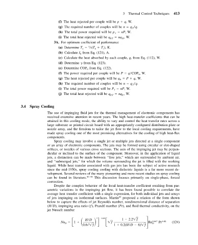
of jets impinging on isothermal surfaces. Martin 49 proposed a relation of the form shown
below to capture the effects of jet Reynolds number, nondimensional distance of separation
(H/D), impinging area ratio (ƒ), Prandtl number (Pr), and fluid thermal conductivity, on the
jet Nusselt number
Nu 1 H/D 0.05 ƒ 1 2.2 ƒ 0.667 0.42
3
D
0.6/ ƒ 1 0.2(H/D 6) ƒ Re D Pr (124)