Page 428 - Mechanical Engineers' Handbook (Volume 4)
P. 428
References  417

                           the structural design, as well as cost, of the jet plate. Since Eqs. (124) and (129) show the
                           jet heat-transfer coefficient to increase with velocity to the 0.67 power, while nozzle pressure
                           losses generally depend on the square of the velocity, concern about the plenum operating
                           pressure would lead the designer to choose the lowest possible jet velocity.
                              Examination of the approximate relation for the jet heat-transfer coefficient, Eq. (129),
                           suggests that to maintain high heat-transfer rates at low jet velocities would necessitate
                           increasing the number of nozzles (n/A), increasing the diameter of each nozzle (D), or
                           decreasing the spacing between the nozzle exit and the component (H). The minimum value
                           of H is likely to be determined by the precision of assembly and deflection under pressure
                           of the jet plate and, thus, it will benefit from reduced operating pressure. Since the maximum
                           heat-transfer rates are approached asymptotically as the total jet area increases to approxi-
                           mately 4% of the component area (see Figure 21), there is coupling between the number of
                           jets and the jet diameter. The heat-transfer rate can, thus, be improved by increasing both
                           jet diameter and the number of jets up to this value, but if operating near the maximum rate,
                           the jet diameter is inversely related to the square root of n/A.
                              In the use of liquid jets, the operating costs are often dominated by the pumping power,
                           or product of total volumetric flow rate and pressure drop, needed to provide a specified
                                                                                       2
                                                                                         3
                           heat-removal rate. The pumping power can be easily shown to vary with D V n/A. Exam-
                           ining this dependence in light of the approximate heat-transfer coefficient relation, Eq. (48),
                           it is again clear that reduced costs are associated with low liquid velocity and a relatively
                           large total nozzle area.
                              These results suggest that optimum performance, based on system-level as well as ther-
                           mal considerations, and as represented by the average heat-transfer coefficient, would be
                           achieved by designing spray cooling systems to provide approximately 4% jet-to-component
                           area ratios and operate at relatively low jet velocities. Improved surface coverage, more
                           uniform heat removal capability, and decreased vulnerability to blockage of a single (or a
                           few) nozzles would appear to be favored by the use of a relatively large number of jets per
                           component, allowing reduction in the diameter of individual jets. Alternately, the cost of
                           manufacturing and the probability of nozzle blockage can be expected to increase for small
                           diameter nozzles and, thus, place a lower practical limit on this parameter. Given the ap-
                           proximate nature of Eq. (129), these relationships must be viewed as indicative, rather than
                           definitive and the complete Martin 49  correlation Eq. (124) should be used for any detailed
                           exploration of these trends.
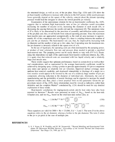
                              Heat-transfer correlations for impingement-cooled, pin-fin heat sinks have also been
                           reported in literature. 54  Results were presented in terms of Nu base , based on the heat-sink
                           footprint area, and on Nu , based on the total heat-sink surface area, as
                                               HS
                                                          Pr               0.210
                                                                   0.689
                                                                        S
                                                               D
                                         Nu base    3.361Re 0.724  0.4  d  d                   (130)
                                                          Pr                      0.181
                                                                    0.689
                                                                           0.678
                                                                        D
                                                               A
                                                                               S
                                          Nu    1.92 Re 0.716  0.4  HS                         (131)
                                            HS
                                                                A d     d      d
                           These equations are valid for 2000   Re   23,000, S/d   2 and 3. The term D in the above
                           equations refers to the jet diameter, whereas d refers to the pin diameter. The term S refers
                           to the jet to jet pitch in the case of multiple jets.
            REFERENCES
                            1. K. J. Negus, R. W. Franklin, and M. M. Yovanovich, ‘‘Thermal Modeling and Experimental Tech-
                              niques for Microwave Bi-Polar Devices,’’ Proceedings of the Seventh Thermal and Temperature
                              Symposium,’’ San Diego, CA, 1989, pp. 63–72.

