
Page 427 - Mechanical Engineers' Handbook (Volume 4)
P. 427
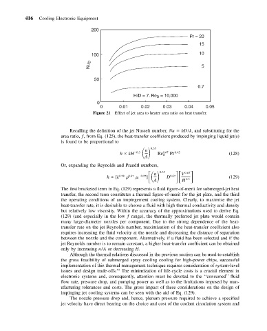
416   Cooling Electronic Equipment

                                      200
                                                                              Pr = 20
                                                                                 15
                                      100                                        10
                                     Nu D                                         5


                                       50
                                                                                 0.7

                                                       H/D = 7. Re  = 10,000
                                                                D
                                        0
                                         0       0.01     0.02     0.03     0.04    0.05
                                       Figure 21 Effect of jet area to heater area ratio on heat transfer.


                             Recalling the definition of the jet Nusselt number, Nu   hD/k, and substituting for the
                          area ratio, ƒ, from Eq. (125), the heat-transfer coefficient produced by impinging liquid jet(s)
                          is found to be proportional to
                                                 h   kH       0.35  0.67  0.42
                                                            n
                                                        0.3
                                                           A     Re D  Pr                    (128)
                          Or, expanding the Reynolds and Prandtl numbers,
                                                            ]     0.35 D
                                                                            0.67
                                                                          V
                                                               n
                                            h   [k 0.58  	 0.67     0.25  0.67               (129)
                                                               A          H  0.3
                          The first bracketed term in Eq. (129) represents a fluid figure-of-merit for submerged-jet heat
                          transfer, the second term constitutes a thermal figure-of-merit for the jet plate, and the third
                          the operating conditions of an impingement cooling system. Clearly, to maximize the jet
                          heat-transfer rate, it is desirable to choose a fluid with high thermal conductivity and density
                          but relatively low viscosity. Within the accuracy of the approximations used to derive Eq.
                          (129) (and especially in the low ƒ range), the thermally preferred jet plate would contain
                          many large-diameter nozzles per component. Due to the strong dependence of the heat-
                          transfer rate on the jet Reynolds number, maximization of the heat-transfer coefficient also
                          requires increasing the fluid velocity at the nozzle and decreasing the distance of separation
                          between the nozzle and the component. Alternatively, if a fluid has been selected and if the
                          jet Reynolds number is to remain constant, a higher heat-transfer coefficient can be obtained
                          only by increasing n/A or decreasing H.
                             Although the thermal relations discussed in the previous section can be used to establish
                          the gross feasibility of submerged spray cooling cooling for high-power chips, successful
                          implementation of this thermal management technique requires consideration of system-level
                          issues and design trade-offs. 53  The minimization of life-cycle costs is a crucial element in
                          electronic systems and, consequently, attention must be devoted to the ‘‘consumed’’ fluid
                          flow rate, pressure drop, and pumping power as well as to the limitations imposed by man-
                          ufacturing tolerances and costs. The gross impact of these considerations on the design of
                          impinging jet cooling systems can be seen with the aid of Eq. (129).
                             The nozzle pressure drop and, hence, plenum pressure required to achieve a specified
                          jet velocity have direct bearing on the choice and cost of the coolant circulation system and