
Page 214 - Mechanics Analysis Composite Materials
P. 214
Chapter 4. Mechanics of a composite layer 199
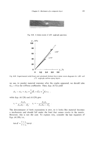
Fig. 4.68. A failure mode of f30" angle-ply specimen.
0, , ma
I-
loo P
80
60
40
20
0 E, ,%
0 0.2 0.4 0.6 0.8
Fig. 4.69. Experimental (solid lines) and calculated (broken lines) stress-strain diagrams for f60" and
f75" angle-ply carbon-epoxy layers.
we use, to predict material response after the cracks appeared, we should take
G12 = 0 in the stiffness coefficients. Then, Eqs. (4.72) yield
1-
All = A12 = A22 = +&) +-El192 ,
4 2
while Eqs. (4.128) and (4.129) give
The denominator of both expressions is zero, so it looks like material becomes
a mechanism and should fail under the load that causes cracks in the matrix.
However, this is not the case. To explain why, consider the last equation of
Eqs. (4.150), Le.,