
Page 211 - Mechanics Analysis Composite Materials
P. 211
196 Mechanics and analysis of composite materials
1
0.8
0.6
0.4
0.2
0 E,%
0 20 40 60 80 100
Fig. 4.63. Calculated (circles) and experimental (solid lines) stress-strain diagrams for f15", f30", f60",
and f75" angle-ply layers.
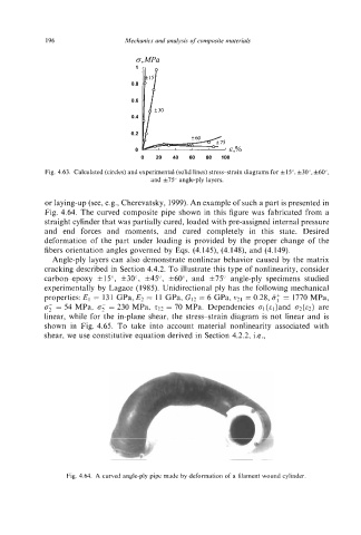
or laying-up (see, e.g., Cherevatsky, 1999). An example of such a part is presented in
Fig. 4.64. The curved composite pipe shown in this figure was fabricated from a
straight cylinder that was partially cured, loaded with pre-assigned internal pressure
and end forces and moments, and cured completely in this state. Desired
deformation of the part under loading is provided by the proper change of the
fibers orientation angles governed by Eqs. (4.145), (4.148), and (4.149).
Angle-ply layers can also demonstrate nonlinear behavior caused by the matrix
cracking described in Section 4.4.2. To illustrate this type of nonlinearity, consider
carbon-epoxy f15", f3W, f45", f60", and f75" angle-ply specimens studied
experimentally by Lagace (1 985). Unidirectional ply has the following mechanical
properties: E1 = 131 GPa, E2 = 11 GPa, G12 = 6 GPa, v21 = 0.28, IT: = 1770 MPa,
8; = 54 MPa, 8, = 230 MPa, 112 = 70 MPa. Dependencies al(el)and Q(E~) are
linear, while for the in-plane shear, the stress-strain diagram is not linear and is
shown in Fig. 4.65. To take into account material nonlinearity associated with
shear, we use constitutive equation derived in Section 4.2.2, Le.,
Fig. 4.64. A curved angle-ply pipe made by deformation of a filament wound cylinder.