
Page 210 - Mechanics Analysis Composite Materials
P. 210
Chapter 4. Mechanics of a composite layer 195
For composite materials, longitudinal strain EI is usually small, and these equations
can be further simplified as follows:
(4.150)
l+E;=(l+Ex)(l+Ey),
1 fEy
tan 4' = -tan 4
1 +EX
As an example, consider a specially synthesized highly deformable composite
material made from glass composite fibers and thermoplastic matrix. Neglecting
interaction of strains we take constitutive equations for the unidirectional ply as
(4.151)
where El in the first equation is the longitudinal elasticity modulus, while E;' in the
denominator takes account of the decrease of the ply stiffness due to increase in
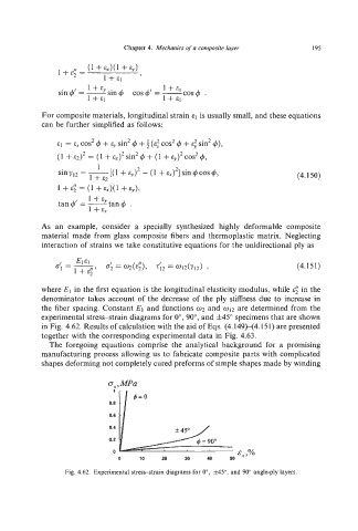
the fiber spacing. Constant E1 and functions 02 and 012 are determined from the
experimental stress-strain diagrams for o",go", and f45" specimens that are shown
in Fig. 4.62. Results of calculation with the aid of Eqs. (4.149H4.151) are presented
together with the corresponding experimental data in Fig. 4.63.
The foregoing equations comprise the analytical background for a promising
manufacturing process allowing us to fabricate composite parts with complicated
shapes deforming not completely cured preforms of simple shapes made by winding
a,,MPa
1
0.8
0.6
0.4
0.2 H I 4 = 90"
0 .,%
0 10 20 30 40 50
Fig. 4.62. Experimental stress-strain diagrams for O", f45", and 90" angle-ply layers.