
Page 213 - Mechanics Analysis Composite Materials
P. 213
198 Mechanics and analysis of composite marerials
1600 -
I E,,%
0 0.4 0.8 1.2 1.6 2 2.4
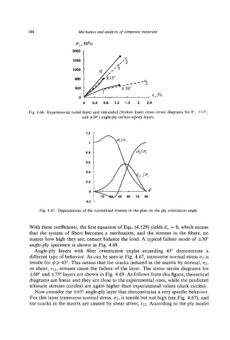
Fig. 4.66. Experimental (solid lines) and calculated (broken lines) stress-strain diagrams for O", fl5",
and f30")angle-ply carbon*poxy layers.
1
0.6
0.6
0.4
0.2
0
Fig. 4.67. Dependencies of the normalized stresses in the plies on the ply orientation angle.
With these coefficients, the first equation of Eqs. (4.129) yields E, = 0, which means
that the system of fibers becomes a mechanism, and the stresses in the fibers, no
matter how high they are, cannot balance the load. A typical failure mode of f30"
angle-ply specimen is shown in Fig. 4.68.
Angle-ply layers with fiber orientation angles exceeding 45" demonstrate a
different type of behavior. As can be seen in Fig. 4.67,transverse normal stress a2 is
tensile for (6>, 45".This means that the cracks induced in the matrix by normal, Q,
or shear, 212, stresses cause the failure of the layer. The stress-strain diagrams for
f60"and f75"layers are shown in Fig. 4.69.As follows from this figure, theoretical
diagrams are linear and they are close to the experimental ones, while the predicted
ultimate stresses (circles) are again higher than experimental values (dark circles).
Now consider the f45"angle-ply layer that demonstrates a very specificbehavior.
For this layer transverse normal stress, u2, is tensile but not high (see Fig. 4.67), and
the cracks in the matrix are caused by shear stress, 212.According to the ply model