Page 27 - Mechanics of Asphalt Microstructure and Micromechanics
P. 27

20   Ch a p t e r  O n e


              1.6.3 Stresses
              1.6.3.1 Cauchy Stress
              Considering an area element ΔS of current configuration, having applied forces Δf i  and
              momentum ΔM i  on it, the Cauchy stress principle asserts that the following limits (as
              the area ΔS approaches zero) exist:

                                              Δf   df
                                           lim  i  =  i  =  t () n               (1-98)
                                           ΔS→0  ΔS  dS  i
                 It is named the stress vector or traction vector.
                                                ΔM
                                             lim   i  = 0                        (1-99)
                                             ΔS→0  ΔS
                 This means that the distributed momentum is equal to zero.

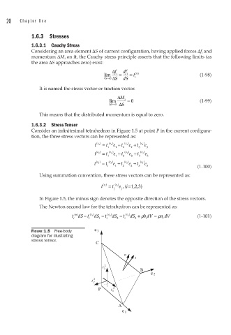
              1.6.3.2 Stress Tensor
              Consider an infinitesimal tetrahedron in Figure 1.5 at point P in the current configura-
              tion, the three stress vectors can be represented as:
                                       t  e ()  =  t  e () e +  t  e () e + t  e () 1  e
                                         1
                                                    1
                                              1
                                            1  1  2   2  3  3
                                       t  e ( 2  )  =  t  e ( 2  ) e +  t  e ( 2  ) e +  t  e ( 2  ) e
                                            1  1  2   2  3  3
                                       t  e ()  =  t  e () 3  e + t  e () e +  t  e () 3  e
                                                    3
                                        3
                                            1  1  2   2  3  3                   (1-100)
                 Using summation convention, these stress vectors can be represented as:
                                          t ()  =  t  () e , ( i=1,2,3)
                                           e i
                                                e i
                                               j  j
                 In Figure 1.5, the minus sign denotes the opposite direction of the stress vectors.
                 The Newton second law for the tetrahedron can be represented as:
                                                               =
                                   −
                               n ()
                              t dS t  e () 1  dS −  t  e ( 2  ) dS − t  e () 3  dS + ρ b dV = ρadV  (1-101)
                               i     i   1  i   2  i   3    i     i
              FIGURE 1.5  Free-body    e 3
              diagram for illustrating
              stress tensor.
                                        C
                                                   n
                                                       t
                                          t  2
                                           3             B
                                                              e 2
                                       2
                                      t
                                       2
                                         P    t  1 2

                                                 A
                                                  e 1
   22   23   24   25   26   27   28   29   30   31   32