
Page 338 - Mechanics of Asphalt Microstructure and Micromechanics
P. 338
330 Ch a p t e r e n
T
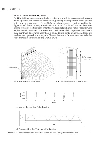
10.2.1.1 Finite Element (FE) Model
An FEM indirect tensile test was built to reflect the actual displacement and traction
boundary of the test. Due to the symmetrical geometry of the specimen, only a quarter
of the sample was modeled (Figure 10.2a, the whole geometry must be used for the
digital model due to non-symmetric microstructure). Distributed traction force was
used to represent the loading in order to avoid contact problems. Roller supports were
applied to each node at the symmetric axis. The location of the displacement measure-
ment point was determined according to actual testing configurations. The loads are
modeled as a repeated haversine pulse. The amplitude and frequency were set to be the
same as those in the actual testing (Figure 10.2c).
p
1"
Deformation
Measure Point
4"
Measuring point
1"
2"
a. FE Model Indirect Tens
1.00
Load 0.50
0.00
0 1 2 3 4 5
Time
c. Indirect Tensile Test Pulse Loading
1
Load 0.5
0
0 1 2 3 4 5
Time
d. Dynamic Modulus Test Sinusoidal Loading
FIGURE 10.2 Model components for indirect tensile test and the dynamic modulus test.