
Page 350 - Mechanics of Asphalt Microstructure and Micromechanics
P. 350
T
342 Ch a p t e r e n
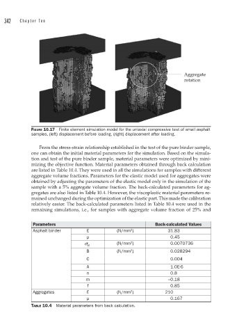
Aggregate
rotation
FIGURE 10.17 Finite element simulation model for the uniaxial compressive test of small asphalt
samples, (left) displacement before loading, (right) displacement after loading.
From the stress-strain relationship established in the test of the pure binder sample,
one can obtain the initial material parameters for the simulation. Based on the simula-
tion and test of the pure binder sample, material parameters were optimized by mini-
mizing the objective function. Material parameters obtained through back calculation
are listed in Table 10.4. They were used in all the simulations for samples with different
aggregate volume fractions. Parameters for the elastic model used for aggregates were
obtained by adjusting the parameters of the elastic model only in the simulation of the
sample with a 5% aggregate volume fraction. The back-calculated parameters for ag-
gregates are also listed in Table 10.4. However, the viscoplastic material parameters re-
mained unchanged during the optimization of the elastic part. This made the calibration
relatively easier. The back-calculated parameters listed in Table 10.4 were used in the
remaining simulations, i.e., for samples with aggregate volume fraction of 25% and
Parameters Back-calculated Values
2
Asphalt binder E (N/mm ) 31.83
μ 0.45
(N/mm ) 0.0070736
2
s yp
2
B (N/mm ) 0.028294
C 0.004
A 1.0E-6
n 0.8
m –0.18
f 0.85
2
Aggregates E (N/mm ) 210
μ 0.167
TABLE 10.4 Material parameters from back calculation.