
Page 286 - Mechanics of Microelectromechanical Systems
P. 286
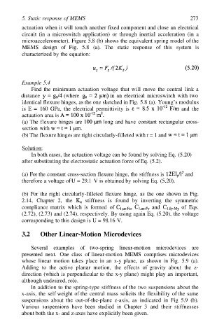
5. Static response of MEMS                                       273
         actuation when it will touch another fixed component and close an electrical
         circuit (in  a  microswitch application)  or through  inertial  acceleration (in  a
          microaccelerometer). Figure 5.8 (b) shows the equivalent spring model of the
          MEMS  design of  Fig. 5.8  (a). The static  response of  this  system is
         characterized by the equation:


         Example 5.4
             Find the  minimum  actuation voltage  that will move  the central  link a
         distance         (where           in an electrical  microswitch with two
          identical flexure hinges, as the one sketched in Fig. 5.8 (a). Young’s modulus
          is  E  =  160 GPa, the electrical  permittivity is           and  the
         actuation area is
          (a) The flexure hinges are     long and have  constant rectangular cross-
          section with
          (b) The flexure hinges are right circularly-filleted with r = 1 and

          Solution:
             In both cases, the actuation voltage can be found by solving Eq. (5.20)
         after substituting the electrostatic actuation force of Eq. (5.2).


         (a) For the constant cross-section flexure hinge, the stiffness is   and
         therefore a voltage of U = 29.1  V is obtained by solving Eq. (5.20).

         (b) For the right circularly-filleted  flexure hinge, as the  one  shown in Fig.
         2.14, Chapter  2,  the   stiffness is  found  by  inverting the  symmetric
         compliance matrix  which is  formed of             and        of  Eqs.
         (2.72), (2.73) and (2.74), respectively. By using again Eq. (5.20), the voltage
         corresponding to this design is U = 98.16 V.

         3.2     Other Linear-Motion Microdevices

             Several examples of  two-spring  linear-motion  microdevices are
         presented  next. One  class of linear-motion  MEMS  comprises microdevices
         whose  linear motion  takes place  in an  x-y plane,  as  shown in Fig.  5.9 (a).
         Adding to  the  active  planar  motion,  the  effects of  gravity  about the z-
         direction (which is perpendicular to the x-y plane) might play an important,
         although undesired, role.
             In addition to the spring-type stiffness of the two suspensions about the
         x-axis, the  self weight of the central mass  solicits the flexibility of the same
         suspensions about  the out-of-the-plane  z-axis,  as  indicated in  Fig 5.9  (b).
         Various  suspensions have  been  studied in Chapter  3  and  their stiffnesses
         about both the x- and z-axes have explicitly been given.