
Page 283 - Mechanics of Microelectromechanical Systems
P. 283
270 Chapter 5
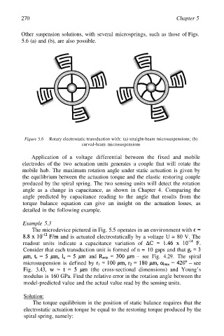
Other suspension solutions, with several microsprings, such as those of Figs.
5.6 (a) and (b), are also possible.
Figure 5.6 Rotary electrostatic transduction with: (a) straight-beam microsuspensions; (b)
curved-beam microsuspensions
Application of a voltage differential between the fixed and mobile
electrodes of the two actuation units generates a couple that will rotate the
mobile hub. The maximum rotation angle under static actuation is given by
the equilibrium between the actuation torque and the elastic restoring couple
produced by the spiral spring. The two sensing units will detect the rotation
angle as a change in capacitance, as shown in Chapter 4. Comparing the
angle predicted by capacitance reading to the angle that results from the
torque balance equation can give an insight on the actuation losses, as
detailed in the following example.
Example 5.3
The microdevice pictured in Fig. 5.5 operates in an environment with
and is actuated electrostatically by a voltage U = 80 V. The
readout units indicate a capacitance variation of
Consider that each transduction unit is formed of n = 10 gaps and that
and – see Fig. 4.29. The spiral
microsuspension is defined by – see
Fig. 3.43, (the cross-sectional dimensions) and Young’s
modulus is 160 GPa. Find the relative error in the rotation angle between the
model-predicted value and the actual value read by the sensing units.
Solution:
The torque equilibrium in the position of static balance requires that the
electrostatic actuation torque be equal to the restoring torque produced by the
spiral spring, namely: