
Page 90 - Mechanics of Microelectromechanical Systems
P. 90
2. Microcantilevers, microhinges, microbridges 77
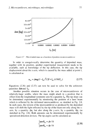
Figure 2.7 Plot of added mass as a function of position on microcantilever
In order to unequivocally determine the quantity of deposited mass,
together with its position, another experimental measurement needs to be
available, such as knowledge of the tip deflection. In this case, the tip
displacement about the z-axis, which is caused by the mass added at point i,
is calculated as:
Equations (2.36) and (2.37) can now be used to solve for the unknown
quantities and
Another possible situation occurs in the case of microcantilevers of
relatively-large widths, where the mass might attach in a position that is
offset from the longitudinal symmetry axis by a quantity The tip slope can
be determined experimentally by monitoring the position of a laser beam
which is reflected by the deformed microcantilever, as sketched in Fig. 2.8.
In such cases, the torsion of the microcantilever as produced by the deposited
mass will shift the light reflected by the tip of the beam not only along the x-
axis, by a quantity but also along the y-axis, by a quantity (as
sketched in Fig. 2.8). Both amounts can be determined experimentally by
specialized detection devices. The tip angles can be calculated as: