
Page 155 - Mechatronic Systems Modelling and Simulation with HDLs
P. 155
144 7 MECHATRONICS
Lambda
Accelerator Idle a NOx value
pedal setting ig
a pe m idle CO value
+
Throttle +
valve m tv HC value
m air a pe
Mixture Gear Kick Kickdown
preparation selection
Lambda Gear
Torque Automatic Wheel Road
generation transmission (rot. -> trans.) gradient
a Torque/ Torque / Force /
m fuel ig rot. vel. rot. vel. velocity Air
Digital n rev friction
controller t
m air rev
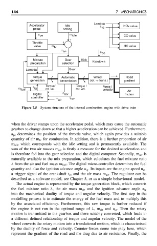
Figure 7.5 System structure of the internal combustion engine with drive train
when the driver stamps upon the accelerator pedal, which may cause the automatic
gearbox to change down so that a higher acceleration can be achieved. Furthermore,
a pe determines the position of the throttle valve, which again provides a suitable
quantity of air m tv for combustion. In addition, there is a further proportion of air
m idle which corresponds with the idle setting and is permanently available. The
sum of the two air masses m air is firstly a measure for the desired acceleration and
is therefore fed into the gear selection and the digital computer. Secondly, m air is
naturally available to the mix preparation, which calculates the fuel mixture ratio
λ from the air and fuel mass m fuel . The digital micro-controller determines the fuel
quantity and also the ignition advance angle a ig . Its inputs are the engine speed n cs ,
a trigger signal of the crankshaft t cs and the air mass m air . The regulator can be
described as a software model, see Chapter 5, or as a simple behavioural model.
The actual engine is represented by the torque generation block, which converts
the fuel mixture ratio λ, the air mass m air and the ignition advance angle a ig
into the mechanical duality of torque and angular velocity. The first step in the
modelling process is to estimate the energy of the fuel mass and to multiply this
by the associated efficiency. Furthermore, this raw torque is further reduced if
the engine is not run in the optimal range of λ,m air and a ig . Then the rotary
motion is transmitted to the gearbox and there suitably converted, which leads to
a different defined relationship of torque and angular velocity. The model of the
wheel converts the rotary motion into a translational motion, which is characterised
by the duality of force and velocity. Counter-forces come into play here, which
represent the gradient of the road and the drag due to air resistance. Finally, the