
Page 157 - Mechatronic Systems Modelling and Simulation with HDLs
P. 157
146 7 MECHATRONICS
Torque
Ignition
angle
40°
30°
20°
0.8 0.9 1 1.1 1.2 10°
Ratio of mixture
Ratio of mixture
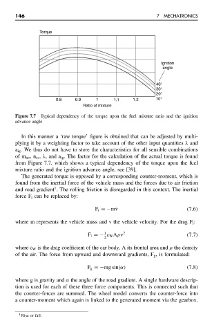
Figure 7.7 Typical dependency of the torque upon the fuel mixture ratio and the ignition
advance angle
In this manner a ‘raw torque’ figure is obtained that can be adjusted by multi-
plying it by a weighting factor to take account of the other input quantities λ and
a ig . We thus do not have to store the characteristics for all sensible combinations
of m air ,n cs , λ, and a ig . The factor for the calculation of the actual torque is found
from Figure 7.7, which shows a typical dependency of the torque upon the fuel
mixture ratio and the ignition advance angle, see [39].
The generated torque is opposed by a corresponding counter-moment, which is
found from the inertial force of the vehicle mass and the forces due to air friction
1
and road gradient . The rolling friction is disregarded in this context. The inertial
force F i can be replaced by:
F i =−m˙v (7.6)
where m represents the vehicle mass and v the vehicle velocity. For the drag F l :
1
F l =− c W Aρv 2 (7.7)
2
where c W is the drag coefficient of the car body, A its frontal area and ρ the density
of the air. The force from upward and downward gradients, F g , is formulated:
F g =−mg sin(α) (7.8)
where g is gravity and α the angle of the road gradient. A single hardware descrip-
tion is used for each of these three force components. This is connected such that
the counter-forces are summed. The wheel model converts the counter-force into
a counter-moment which again is linked to the generated moment via the gearbox.
1 Rise or fall.