
Page 162 - Mechatronic Systems Modelling and Simulation with HDLs
P. 162
7.4 DEMONSTRATOR 3: CAMERA WINDER 151
where the angular velocities ω A and ω B are in a fixed ratio of α, the moments M A
and M B are in a fixed ratio of 1/α and furthermore the efficiency η is taken into
account. Thus there is nothing further standing in the way of a direct implementa-
tion of the model in VHDL-AMS or another hardware description language.
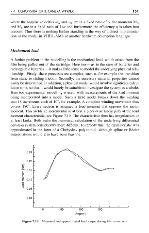
Mechanical load
A further problem in the modelling is the mechanical load, which arises from the
film being pulled out of the cartridge. Here too — as in the case of batteries and
rechargeable batteries — it makes little sense to model the underlying physical rela-
tionships. Firstly, these processes are complex, such as for example the transition
from static to sliding friction. Secondly, the necessary material properties cannot
easily be determined. In addition, a physical model would involve significant calcu-
lation time, so that it would barely be suitable to investigate the system as a whole.
Here too experimental modelling is used, with measurements of the load moment
being incorporated into a model. Such a table model breaks down the winding
◦
into 18 increments each of 10 , for example. A complete winding movement thus
◦
covers 180 . Every section is assigned a load moment that opposes the motor
moment. This yields an incremental or at best a piece-wise linear path of the load
moment characteristic, see Figure 7.10. The characteristic thus has irregularities or
at least kinks. Both make the numerical calculation of the underlying differential
equation system considerably more difficult. To remedy this, the characteristic was
approximated in the form of a Chebyshev polynomial, although spline or B´ ezier
interpolations would also have been feasible.
0.24
0.20
Load moment [Nm] 0.16
0.12
0.08
0.04
0 50 100 150
Angle [°]
Figure 7.10 Measured and approximated load torque during film movement