
Page 164 - Mechatronic Systems Modelling and Simulation with HDLs
P. 164
7.5 DEMONSTRATOR 4: DISK DRIVE 153
even allows us to assess functionality spread over all these domains. One example
of this is track following and track seeking for the read/write-head.
Moreover, this section details the resulting electronics design methodology. For
instance, it will be shown how key system properties, e.g. seek time, can be deter-
mined by means of the mixed simulation of mechanics, electronics and firmware. In
addition, the same simulation environment is used to realistically verify analogue
and digital circuitry as well as firmware.
7.5.2 The disk drive
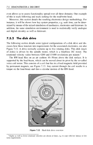
The following section details some typical configurations of a disk drive and dis-
cusses how these translate into requirements for the associated electronics, see also
Figure 7.12. A drive normally contains up to five rotating disks. This disk (stack
of disks) is driven by the spindle motor, which is a brushless DC motor. The
rotational velocity varies between 4200 and 15 000 revolutions per minute. 2
The RW-head flies on an air cushion 10–50 nm above the disk surface. It is
supported by the load-beam, which can be moved about its pivot by the so-called
voice coil motor. This consists of a coil that lies in a fixed magnetic field provided
by permanent magnets, see Figure 7.13. Any current through the coil results in a
torque on the load-beam and thus a circular motion of the RW-head.
Spindle motor
+
+ +
RW-Head
+
Disk(s)
Voice coil motor
Loadbeam
Pivot
Figure 7.12 Hard disk drive overview
2 Higher as well as lower rotational velocities are chosen at times, e.g. to cope with low latency or low
noise requirements.